
RRC ( Radio Resource Control )
Radio resource
control (RRC) is the highest layer in the control plane of the access
stratum (AS). It also transfers messages of the non‐access stratum (NAS), which
is located above the RRC layer. Signalling provided the RRC layer has
the following characteristics such as higher extensibility, secured
transmission, reliable transmission and longer processing delay. The RRC layer
performs the following functions such as broadcast of system information,
paging, establishment/release of an RRC connection, transfer of NAS
information, AS security configuration, transfer of UE radio access capability,
measurement configuration and reporting and mobility control.
Function:
1.
System information broadcasting :
System
Information is divided into Master Information Block (MIB) and a number of
System Information Blocks (SIB1- SIB12). UE needs to locate and read the system
information before establishing any connection to the E-UTRA.
The
first duty is when the UE is switched ON, for first time synchronization UE has
to read the PLMN ID which is present in the SIB1(System information block type
1) and find out the which network UE has to latch.The network(e-NB RRC layer)
is broadcasts this information in the form of MIBs and SIBs to help the
UEs in their selection processes.
MIB :
It
contains cell bandwidth(n6,n15, n25, n50, n100) and
information about PHICH and the SFN (System Frame
Number). SFN is very much important to read SIB1.
The MIB
is transmitted using a physical layer channel called PBCH or Physical Broadcast
Channel on downlink.
The MIB
is a 24 bit information with following information within.
- 3
bits for system bandwidth
-
3 bits for PHICH information (1 bit to
indicate normal or extended PHICH and 1 bit to indicate the PHICH Ng value )
-
8 bits for system frame number
-
10 bits are reserved for future use
According
to 36.331 section 5.2.1.2, the MIB scheduling is as follows :
The MIB
uses a fixed schedule with a periodicity of 40 ms and repetitions
made within 40 ms. The first transmission of the MIB is scheduled in subframe
#0 of radio frames for which the SFN mod 4 = 0, and repetitions are
scheduled in subframe #0 of all other radio frames.
New MIB
is broadcasted every radio frame for which SFN mod 4 = 0 (40ms repetition)
while repeated MIBs are broadcasted in the middle 10ms radio frames as shown in
the figure below-

Why PHICH is carried by MIB?
After decoding MIB, UE has to decode PDCCH to read
other system information blocks (SIBs). PDCCH, PHICH and PCFICH share the
resources in the control region of a subframe. So to find the available
resources for PDCCH, UE has to know the PHICH configuration only, as PCFICH
resources are fixed and known.
SIB:
SIBs
carry relevant information for the UE, which helps UE to access a
cell, perform cell re-selection, information related to INTRA-frequency,
INTER-frequency and INTER-RAT cell selections etc.
There are 13 types of SIBs. Each SIB
has carry own information.
- Minimum two SIBs that is SIB1 and SIB2 are
required for the UE to initiate Attach procedure.
- SIB3 -SIB8 are required to perform the handover etc.
When UE
read the SIBs :
· - UE is powered on (selecting a cell)
· -
Cell re-selection
· - After
HO completion
· -
After entering E-UTRAN from another RAT
· -
coming out of OUT OF COVERAGE situation
· -
receiving a notification that SYSTEM INFORMATION has changed
· -
receiving an indication about the presence of ETWS (Primary/Secondary), CMAS
notification
· -
receiving a request from CDMA 2000 upper layers
· -
exceeding the maximum validity duration of SIBs
SIB1:
SIB1 broadcasts common information to all
UEs in the cell related to cell access parameters and information related to
scheduling of remaining SIBs.
SIB1 is broadcasted in subframe # 5 in the SFN
for which SFN mod 8 = 0. While the repeated copies are sent in subframe # 5 for
which SFN mod 2 = 0 . Thus the new copy of SIB1 is transmitted every 80ms as
shown below-
According to 36.331 section 5.2.1.2, the SIB1
scheduling is as follows :
The SystemInformationBlockType1 uses a fixed
schedule with a periodicity of 80 ms and repetitions made within 80 ms.The
first transmission of SystemInformationBlockType1 is scheduled in subframe #5
of radio frames for which the SFNmod 8 = 0, and repetitions are scheduled in
subframe #5 of all other radio frames for which SFN mod 2 = 0.

Information element of SIB1:
Cell Access Related Information
|
PLMN
Identity List
= MCC(2 or 3 digits) + MNC(3 digits) |
A PLMN ID is an ID that globally identifies a mobile operator (e.g. combination of MCC
(405) and MNC (853) for idea west Bengal in India).Mobile Network Code, assigned
by National Authority and Mobile Country Code, assigned by ITU.
|
Cell
Reserved for Operator use
|
As defined by operator (Reserved/Not Reserved).
-Not Reserved means all the UE treat the cell
as a candidate for the cell selection and ell reselection.
-Reserved means UE with Access Class 11 or 15
operating in their HPLMN treat the cell as a candidate for cell selection and
reselection. UE with Access Class 0 to 9, or 12 to 15 treat the cell as barred.
Barred means UE are not allowed to select or reselect the cell (not even for
emergency calls)
If
the cell is Closed Subscriber Group (CSG) cell then UE are allowed to select
another cell on the same frequency. If the cell is not a CSG cell then the UE
has to check the ‘intra frequency reselection’ information SIB1 to determine whether
it is allowed to select another cell on the same frequency or not. |
|
Tracking
Area Code
|
Each e-NB broadcasts a special tracking area
code (TAC) to indicate to which Tracking Area the e-NB belong to and the TAC is
unique within a PLMN. (Since PLMN is a unique number allocated to each of the
system operator and TAC is a unique in a PLMN, if you combine these two numbers
you would have a globally unique number. This number (PLMN + TAC) is called
Tracking Area Identity (TAI).
|
|
Cell
Identity
|
Identifies a cell within the PLMN
|
|
Cell
Barred
|
If Barred then UE is not allowed to camp on the
cell
|
|
Intra Frequency
Reselection
|
If enabled, UE will be able to perform
Cell-reselection to INTRA-frequency cells
|
|
CSG
Indication
|
CSG is a set of user (UEs, Subscribers) which
allowed for a specific cell (usually Femto cell). The cell with CSG Indication
set to be 'TRUE' is called 'CSG Cell'.
Non CSG Cell (Ordinary Cell) allows any UE to camp on as long
as the UE has proper PLMN info and the cell is not barred, but CSG Cell allows
only UEs belonging to a specific CSG.
|
|
CSG
Identity
|
If the cell with CSG Identity is set to be 'absent' is called 'Normal Cell'. If the cell with CSG Identity is set to be 'Present' is called 'CSG Cell'.
|
|
P-Max
|
Value applicable for the cell. If absent the UE
applies the maximum power according to the UE capability. If e-NB configures
the value more than the value supported by the UE then UE will set the max
value supported by the UE capability. Example UE Category 3 supports max 23 db.
|
|
Cell Selection Information
|
q-Rx-LevMin
|
The minimum RSRP [Range is around -44dbm (good) to -140dbm(bad) ]
requirement for cell selection is defined as
q-Rx-LevMin.
|
q-Rx-LevMinoffset
|
The signalledvalues Qrxlevminoffset and Qqualminoffset are only applied when a cell is evaluated for cell selection as a result of a periodic search for a higher priority PLMN while camped normally in a VPLMN. During this periodic search for higher priority PLMN the UE may check the S criteria of a cell using parameter values stored from a different cell of this higher priority PLMN.
|
|
It indicates the E-UTRA operating band that means on which band cell is
operating. In SIB1 carries optional IE “Multi band info list” which informs the
list of band are overlapping with the band, current cell is operating.
|
||
Scheduling Information List
|
SI Map
Information
|
List of the SIBs mapped to this System
Information message. There is no mapping information of SIB2, it is always
present in the first System Information message listed in the scheduling Info List.
|
SI
Periodicity
|
Periodicity of System Information Blocks except than SIB1. For
example rf8 denotes 8 radio frames, rf16 denotes 16
radio frames, and so on.
|
|
SI Window Length
|
It tells the UE that SI information should be
present within this duration starting from the sub-frame of the Radio
frame decided from SI periodicity. Its value is in milli second. For example 20ms.
|
|
System
Information value tag
|
||
LTE cell Selection Criterion :
Cell Selection
procedure allows the UE to camp on to a cell. There are three types of Cell
selection in LTE:
1. Initial cell selection: UE scans all frequencies
2. Stored information cell selection: Stored list available with UE (earlier camed on cell). This can be also vendor specific implementation; like how each one of them would like to optimise the stored information cell selection
3. "Redirected carrier information" in RRC_Connection_Release message
Working:
- RRC asks PHY to scan frequencies and report
cells.
- Once when UE PHY scans the UE supported
frequencies and reports the found out cells during the scan, the results are
reported to UE RRC along with their Cell IDs and the Cell specific Power values
(RSRP, RSRQ).
- UE RRC will select the strongest Cell ID from
the list and then will go for Cell validation procedure
- When the selected Cell ID passes the cell
validation procedure, the UE camps onto it and proceeds to decode the broadcast
information (MIB, SIBs). It is during this procedure, that the below mentioned
calculations take place:
The cell
selection criterion S is fulfilled when:
Srxlev > 0 AND Squal > 0
where:
Srxlev = Qrxlevmeas – (Qrxlevmin + Qrxlevminoffset) – Pcompensation
Squal = Qqualmeas – (Qqualmin + Qqualminoffset)
Srxlev > 0 AND Squal > 0
where:
Srxlev = Qrxlevmeas – (Qrxlevmin + Qrxlevminoffset) – Pcompensation
Squal = Qqualmeas – (Qqualmin + Qqualminoffset)
where:
Srxlev
|
Cell selection RX level value (dB)
|
Squal
|
Cell selection quality value (dB)
|
Qrxlevmeas
|
Measured cell RX level value (RSRP)
|
Qqualmeas
|
Measured cell quality value (RSRQ)
|
Qrxlevmin
|
Minimum required RX level in the cell (dBm)
|
Qqualmin
|
Minimum required quality level in the cell
(dB)
|
Qrxlevminoffset
|
Offset to the signalled Qrxlevmin taken into account
in the Srxlev evaluation as a result of a periodic search for a higher
priority PLMN while camped normally in a VPLMN
|
Qqualminoffset
|
Offset to the signalled Qqualmin taken into account in
the Squalevaluation as a result of a periodic search for a higher priority
PLMN while camped normally in a VPLMN
|
Pcompensation
|
max(PEMAX –PPowerClass, 0) (dB)
|
PEMAX
|
Maximum TX power level an UE may use when transmitting
on the uplink in the cell (dBm)
|
PPowerClass
|
Maximum RF output power of the UE (dBm) according to
the UE power class as defined in
|
The signalled
values Qrxlevminoffset and Qqualminoffset are only
applied when a cell is evaluated for cell selection as a result of a periodic
search for a higher priority PLMN while camped normally in a VPLMN. During this
periodic search for higher priority PLMN the UE may check the S
criteria of a cell using parameter values stored from a different cell of
this higher priority PLMN.
SIB2:
There is no mapping information of SIB2. it is
always
present
in the first SystemInformation message listed in the schedulingInfoList list.
SIB2 carried information-


List of
carried information from the network to UE through SIB2:
AC-Barring For Emergency: the emergency call barring status
of access class 10, indicating whether UEs of access class 10 can initiate
emergency calls or not.
AC-Barring For MO-Signalling: access barring information for signalling.
ac-Barring Factor: indicates the access probability factor for signalling.
ac-Barring Time: indicates the average access barring duration for signalling.
ac-Barring For Special AC: “false” or ”true”. Signalling is applied for special Access classes (CSFB, Vo-LTE etc.).
AC-Barring for MO-Data: access barring information for mobile-originated calls.
ac-Barring Factor: indicates the access probability factor for mobile-originated calls.
ac-Barring Time: indicates the average access barring duration for mobile-originated calls.
ac-Barring For Special AC: “false” or ”true”. Mobile-originated call is applied for special Access classes (CSFB, Vo-LTE etc.).
RACH Config Common: contains parameters related to RACH configuration at the MAC
level across the cell.
Number Of RA-Preambles: number of non-dedicated random access preambles.
Size Of RA-Preambles Group-A: number of non-dedicated random access preambles in Random Access Preambles group A.
Message Size Group-A: threshold for determining the size of message when a UE selects a preamble from random access preamble group A during a random access procedure.
Message Power Offset Group-B: power offset for selection preambles from Group B.
Power Ramping Parameters: indicates the steps for UE power where random access preambles is increased each time after a RACH access failure.
Power Ramping Step: if multiple attempts to access the PRACH fail, the UE increases power for random access preambles by a step specified by this parameter.
Preamble Initial Received Target Power: initial UE transmit power for the PRACH which is expected by the e-NB.
Preamble Trans Max: maximum number of preamble transmission to achieve success.
RA Response Window Size: duration of RA response window.
MAC Contention Resolution Timer: time when a UE waits for Msg4 during a random access procedure. This timer starts when a UE initially sends or resends Msg3.
Max HARQ Msg3 Tx: Maximum number of Msg3 HARQ transmissions.
BCCH Config: configuration information of the Broadcast Control Channel.
Modification Period Coeff: modification period coefficient for the BCCH. BCCH modification period is equal to Modification period coefficient multiplies default DRX cycle.
Modification Period Coeff: modification period coefficient for the BCCH. BCCH modification period is equal to Modification period coefficient multiplies default DRX cycle.
PCCH Config: configuration information of the Paging Control Channel.
Default Paging Cycle: default paging period for the cell. It is also known as DRX cycle.
nB: number of paging occurrences within a paging period.
Default Paging Cycle: default paging period for the cell. It is also known as DRX cycle.
nB: number of paging occurrences within a paging period.
PRACH Config: configuration information of the Physical
Random Access Channel.
Root Sequence Index: used to determine 64 physical RACH preamble sequences available in the cell.
PRACH Config Index: this provides the exact position of random access preamble when needs to be send by UE.
High Speed Flag: indicates the speed flag of the cell where the cell serves high-speed railway or other scenarios.
Zero Correlation Zone Config.: indicates the length index for the Zadoff-Chu sequence that generates the random access preamble.
PRACH Freq Offset: shows starting frequency-domain position of the PRACH Physical Resource Blocks.
PDSCH Config Common: contains parameters related to configuration of PDSCH.
Reference Signal Power: cell reference signal or also known as energy per resource element for reference signal.
Pb: used to calculate power difference between Reference Signal and PDSCH.
Reference Signal Power: cell reference signal or also known as energy per resource element for reference signal.
Pb: used to calculate power difference between Reference Signal and PDSCH.
PUSCH Config Common: contains parameters related to PUSCH configuration.
n-SB: indicates the number of PUSCH sub-bands.
Hopping Mode: Inter Sub-Frame, Intra and Inter Sub-Frame, indicates the hopping mode of the PUSCH.
PUSCH Hopping Offset: indicates the hopping offset of the PUSCH (0-98).
Enable 64QAM: indicates whether 64QAM of the PUSCH is enabled (true/false).
Group Hopping Enabled: indicates whether group hopping of the PUSCH is enabled (true/false).
Group Assignment PUSCH: indicates the group assignment of the PUSCH (0-29).
Sequence Hopping Enabled: indicates whether sequence hopping of the PUSCH is enabled (true/false).
Cyclic Shift: indicates the cyclic shift to use for deriving the uplink demodulation reference signal from the base sequence.
PUCCH Config Common: contains parameters related to common PUCCH configuration.
Delta PUCCH Shift: indicates the interval between cyclic shifts used for the PUCCH.
nRB CQI: denotes the bandwidth in terms of resource blocks that are available for use by PUCCH formats 2/2a/2b transmission in each slot.
nCS AN: number of cyclic shift used for PUCCH formats 1/1a/1b in a resource block used for a mix of formats 1/1a/1b and 2/2a/2b.
n1PUCCH AN: parameter used to determine resources used for transmission of PUCCH format 1/1a/1b and 2/2a/2b.
Sounding RS UL Config Common: this parameter indicates whether
UL Sounding RS is enabled (TRUE) or not (FALSE).
srs-Bandwidth Config: denotes an index into tables with cell specific SRS Bandwidth Configuration.
ackNackSRS-Simultaneous Transmission: defines whether a UE can simultaneously transmit SRS and ACK/NACK (true) or not (false).
srs-Bandwidth Config: denotes an index into tables with cell specific SRS Bandwidth Configuration.
ackNackSRS-Simultaneous Transmission: defines whether a UE can simultaneously transmit SRS and ACK/NACK (true) or not (false).
Uplink Power Control Common: contains
parameters used for computing UL power.
p0 Nominal PUSCH: the parameter used to compute the UL UE transmit power for transmission on PUSCH for semi-persistent grants.
Alpha: used to compute the UL UE transmit power for transmission on PUSCH.
p0 Nominal PUCCH: the parameter used to compute the UL UE transmit power for transmission on PUCCH.
Delta Preamble Msg3: the parameter used to compute the UL UE transmit power for transmission of random access response grant.
UL Cyclic Prefix Length: value len1 corresponds to normal CP and len2 corresponds to extended CP.
UE Timers and Constants: set of proposed RRC timers and constant parameters.
T300: interval between subsequent transmissions of RRC Connection Request.
T301: interval between subsequent transmissions of RRC Connection Reestablishment Request.
T310: radio link failure declaration timer (*N310 out of sync indications).
N310: number of consecutive “out-of-sync” indications received from lower layers that triggers timer T310.
T311: radio link failure recovery timer (connection re-establishment procedure).
N311: number of consecutive “in-sync” indications received from lower layers that stops timer T310.
UL Bandwidth: uplink transmission bandwidth. n6 corresponds to 6 resource
blocks, n15 to 15 resource blocks and so on.
Additional Spectrum Emission: the additional spectrum emission, which restricts the emission power of the UEs in the cell.
Time Alignment Timer Common: length of the uplink time alignment timer for UEs in the cell. A UE is considered not time-aligned in the uplink if the timer expires.
SIB3:Additional Spectrum Emission: the additional spectrum emission, which restricts the emission power of the UEs in the cell.
Time Alignment Timer Common: length of the uplink time alignment timer for UEs in the cell. A UE is considered not time-aligned in the uplink if the timer expires.

Cell Re-selection Info Common:
q-Hyst: hysteresis value applied to serving cell for evaluating cell-re selection ranking criteria. It is for cell re-selection when RSRP values are used in the evaluation.
t-Evaluation: specifies the duration for evaluation. Value in seconds.
t-Hyst Normal: the additional duration for evaluating criteria to enter normal mobility state. Specifies the additional time period for evaluating criteria to enter Normal-mobility state. Value in seconds, s30 corresponds to 30 seconds and so on.
n-cell Change Medium: specifies the number of cell re-selections within t-Evaluation to enter Medium-mobility state.
n-cell Change High: specifies the number of cell re-selections within t-Evaluation to enter High-mobility state.
sf-Medium: speed-dependent scaling factor for Qhyst in Medium-mobility state.
sf-High: speed-dependent scaling factor for Qhyst in High-mobility state.
Cell Re-selection Serving Frequency Info:
s-NonIntra Search: measurement triggering threshold for inter-frequency and inter-RAT measurements with lower or equal priority. Actual value in dB is obtained by multiplying by 2.
Thresh Serving Low: threshold for serving frequency used in evaluation of re-selection towards lower priority E-UTRAN frequency. Actual value in dB is obtained by multiplying by 2.
Cell Re-selection Priority: cell re-selection priority of the serving frequency. 0 indicates the lowest priority.
Intra-Freq Cell Re-selection Info:
q-RxLev Min: minimum required received RSRP level for intra-frequency E-UTRA cell re-selection. Actual value in dBm is obtained by multiplying by 2.
p-Max: this parameter is used to limit the allowed UE uplink transmission power on the serving cell.
s-Intra Search: indicates the measurement triggering threshold for re-selection to intra-frequency cells.
Allowed Meas Bandwidth: indicates the measurement bandwidth on the serving frequency on which the UE camps. It is used in intra-frequency measurements for cell re-selection.
Presence Antenna Port1: indicates whether all the intra-frequency neighboring cells are configured with at least two antenna ports:
– TRUE when all the intra-frequency neighboring cells are configured with at least two antenna ports.
– FALSE when one of the intra-frequency neighboring cells is configured with only one antenna port.
Neigh Cell Config: provides the information related to MBSFN and TDD UL/DL configuration of neighbor cells:
– “00” some neighboring cells have the same MBSFN sub-frame configuration as the serving cell.
– “01” none of the neighboring cells is configured with MBSFN sub-frames.
– “10” MBSFN sub-frame configurations of all neighboring cells are the same as the serving cell.
– “11” some neighboring cells have different UL-DL configurations from the serving TDD cell.
t-Reselection EUTRA: cell reselection timer for intra frequency E-UTRA cell reselection. Value in seconds.
sf-Medium: specifies scaling factor for intra-frequency t-Reselection EUTRA in Medium-mobility state. Value oDot25 corresponds to 0.25, oDot5 corresponds to 0.5 etc.
sf-High: specifies scaling factor for intra-frequency t-Reselection EUTRA in High-mobility state. Value oDot25 corresponds to 0.25, oDot5 corresponds to 0.5 etc.
SIB4:

SIB5:sf-Medium: specifies scaling factor for intra-frequency t-Reselection EUTRA in Medium-mobility state. Value oDot25 corresponds to 0.25, oDot5 corresponds to 0.5 etc.
sf-High: specifies scaling factor for intra-frequency t-Reselection EUTRA in High-mobility state. Value oDot25 corresponds to 0.25, oDot5 corresponds to 0.5 etc.
SIB4:

Intra Freq Neigh Cell List: contains LTE cell neighbor list with specific parameters.
Phys Cell Id: indicates the physical cell ID of the intra-frequency neighbor cell.
q-Offset Cell: offset for the intra-frequency neighboring cell, which is used in evaluation for cell re-selections. A larger value of this parameter results in a lower probability of cell re-selections. If this parameter is not set to dB0, it is delivered in SIB4.
Intra Freq Black Cell List: consists of the parameters related to a blacklisted intra-frequency cell.
Phys Cell Id: starting physical cell ID of the intra-frequency blacklisted cell.
Phys Cell Id Range: physical cell ID range of the intra-frequency blacklisted cell.
CSG Phys Cell Id Range: Set of physical cell identities reserved for CSG cells. The received csg-PhysCellIdRange applies if less than 24 hours has elapsed since it was received and the UE is camped on a cell of the same primary PLMN where this field was received.
Note: CSG (Closed Subscriber Group) is a group of users who are allowed for a specific cell (usually Femto cell). A CSG cell has restrictions on UE access. It broadcasts a specific CSG ID in the SIB and only those UEs of the group can access the CSG cell.

Inter Freq Carrier Freq List: contains information about inter-frequency cell re-selection within E-UTRAN.
dl-Carrier Freq: indicates target frequency EARFCN for inter-frequency cell re-selection.
q-RxLev Min: required minimum received RSRP level on this E-UTRA frequency carrier. Actual value in dBm is obtained by multiplying by 2.
q-RxLev Min: required minimum received RSRP level on this E-UTRA frequency carrier. Actual value in dBm is obtained by multiplying by 2.
p-Max: this parameter is used to limit the allowed UE uplink transmission power on this carrier frequency.
t-Reselection EUTRA: cell reselection timer for inter-frequency cell reselection to this E-UTRA frequency carrier.
sf-Medium: specifies scaling factor for t-Reselection EUTRA for inter-frequency reselection to this frequency carrier in Medium-mobility state. Value oDot25 corresponds to 0.25, oDot5 corresponds to 0.5 etc.
sf-High: specifies scaling factor for t-Reselection EUTRA for inter-frequency reselection to this frequency carrier in High-mobility state. Value oDot25 corresponds to 0.25, oDot5 corresponds to 0.5 etc.
threshX-High: inter frequency high priority threshold, the threshold used when reselecting from a lower priority LTE frequency to higher priority LTE frequency. Actual value in dB is obtained by multiplying by 2.
threshX-Low: inter frequency lower priority threshold, the threshold used when reselecting from a higher priority LTE frequency to lower priority LTE frequency. Actual value in dB is obtained by multiplying by 2.
Allowed Meas Bandwidth: indicates the measurement bandwidth of the inter-frequency neighboring cell on the frequency. A cell bandwidth is also expressed in units of physical resource blocks. Cell bandwidths 1.4 MHz, 3 MHz, 5 MHz, 10 MHz, 15 MHz, and 20 MHz correspond to 6 RBs, 15 RBs, 25 RBs, 50 RBs, 75 RBs, and 100 RBs.
Presence Antenna Port1: indicates whether all the inter-frequency neighboring cells are configured with at least two antenna ports:
– TRUE when all the inter-frequency neighboring cells are configured with at least two antenna ports.
– FALSE when one of the inter-frequency neighboring cells is configured with only one antenna port.
– TRUE when all the inter-frequency neighboring cells are configured with at least two antenna ports.
– FALSE when one of the inter-frequency neighboring cells is configured with only one antenna port.
Cell Reselection Priority: inter-frequency cell re-selection priority indicates priority of the neighboring E-UTRAN frequency. The value 0 indicates the lowest priority.
Neigh Cell Config: provides the information related to MBSFN and TDD UL/DL configuration of inter-frequency neighbor cells:
– “00” inter-frequency neighboring cells have the same MBSFN sub-frame configuration as the serving cell.
– “01” none of the inter-frequency neighboring cells is configured with MBSFN sub-frames.
– “10” MBSFN sub-frame configurations of all inter-frequency neighboring cells are ame as the serving cell.
– “11” some inter-frequency neighboring cells have different UL-DL configurations from serving TDD cell.
q-Offset Freq: offset applicable between serving and this frequency carrier. Actual value in dBm is obtained by multiplying by 2. A larger value of this parameter results in a lower probability of reselection to cells on the neighboring E-UTRAN frequency. A smaller value of this parameter leads to the opposite effects.
Inter Freq Black Cell List: consists of the parameters related to a blacklisted inter-frequency cell.
Phys Cell Id: starting physical cell ID of the inter-frequency blacklisted cell.
Phys Cell Id Range: physical cell ID range of the inter-frequency blacklisted cell.
SIB6 :
Carrier Freq List UTRA-FDD: contains information about UTRA FDD frequency carriers relevant for inter-RAT cell re-selection from E-UTRA to UTRAN FDD.
DL Carrier Freq: indicates the DL UARFCN of the neighboring cell on the UTRAN frequency.
threshX-High: UTRAN high priority threshold, the threshold used when reselecting from a lower priority LTE frequency to higher priority UTRAN frequency. Actual value in dB is obtained by multiplying by 2.
threshX-Low: UTRAN lower priority threshold, the threshold used when reselecting from a higher priority LTE frequency to lower priority UTRAN frequency. Actual value in dB is obtained by multiplying by 2.
q-RxLevmin: required minimum received RSCP level on this UTRA frequency carrier. Actual value in dBm is obtained by multiplying by 2 plus 1.
q-QualMin: minimum quality level (EcNo) required for a cell on the UTRAN frequency to become a candidate for reselection.
p-MaxUTRA: this parameter is used to limit the allowed UE uplink transmission power on this UTRA FDD carrier frequency.
t-ReselectionUTRA: indicates the evaluation period for a UE to determine whether to reselect a neighboring UTRAN cell to camp on.
sf-Medium: specifies scaling factor for t-ReselectionUTRA for inter-RAT reselection to UTRA in Medium-mobility state. Value oDot25 corresponds to 0.25, oDot5 corresponds to 0.5 etc.
sf-High: specifies scaling factor for t-ReselectionUTRA for inter-RAT reselection to UTRA in High-mobility state. Value oDot25 corresponds to 0.25, oDot5 corresponds to 0.5 etc.
SIB7:

t-Reselection GERAN: cell reselection timer for reselection to a GERAN frequency carrier. Value in seconds.
sf-Medium: specifies scaling factor for t-Reselection GERAN for inter-RAT reselection to GERAN in Medium-mobility state. Value oDot25 corresponds to 0.25, oDot5 corresponds to 0.5 etc.
sf-High: specifies scaling factor for t-Reselection GERAN for inter-RAT reselection to GERAN in High-mobility state. Value oDot25 corresponds to 0.25, oDot5 corresponds to 0.5 etc.
Carrier Freqs Info List GERAN: parameters related to a neighboring GERAN frequency group, these parameters are used for Inter-Technology reselection from EUTRAN to GERAN. The parameters might be different set for each frequency group.
Starting ARFCN: specifies first ARFCN in GERAN frequency group.
Band Indicator: specifies GERAN frequency band, either it is GSM1800 or GSM1900.
Explicit List Of ARFCNs: specifies the ARFCN list of the GERAN BCCH.
Cell Reselection Priority: indicates the cell reselection priority of GERAN frequency group. The value 0 indicates the lowest priority.
NCC-Permitted: field encoded as a bit map, where bit N is set to “0” if a BCCH carrier with NCC = N-1 is not permitted for monitoring and set to “1” if a BCCH carrier with NCC = N-1 is permitted for monitoring; N = 1 to 8; bit 1 of the bitmap is the leading bit of the bit string.
q-RxLevMin: required minimum received RSSI level on GERAN frequency carrier for re-selection from LTE to GSM. Actual value in dBm is value * 2 – 115.
Pmax: this parameter is used to limit the allowed UE uplink transmission power on this GERAN carrier frequency.
threshX-High: threshold used when reselecting from lower priority LTE frequency to higher priority GERAN frequency group. Actual value in dB is obtained by multiplying by 2.
threshX-Low: threshold used when reselecting from higher priority LTE frequency to lower priority GERAN frequency group. Actual value in dB is obtained by multiplying by 2.
SIB 1-13 :

Handover:
Configuration:

Steps:
1. Source e-NB:
Ø First start the power of the e-NB.
Ø Backhaul: One LAN cable(From e-NB) is connected
to Backhaul side. Backhaul means acting as core network/server
(MME/HSS/SGW/PGW).
Ø Laptop: Another LAN cable (From e-NB) is used
for data which is connected to LAPTOP. Data means accessing the file system.
For example, if we need TCP Dump/ Backup
file of that e-NB, through this LAN cable we can get this Backup file/TCP Dump
for future purpose. Suppose e-NB file has got corrupted, manually we can upload
Backup file/TCP Dump to the e-NB.
Once LAN cable is connected to LAPTOP
then we will established WinSCP between
them using static IP. Then only we can upload the file to the e-NODE. We can also
connect through serial cable whether the e-NB UP or Down but serial cable is only for
logging purpose.Through serial cable we are unable to upload file to the e-NODE.
This will be possible only through the LAN cable/data cable.

- Now, LAPTOP is connected with e-NB through LAN. Then we will go to Config file(4/5 line) for that particular e-NB present inside the file system. We need to select that Config file and insert/push in to e-NB and then we need to reboot the e-NB through Linux command. Once reboot is done successfully then e-NB goes up/ or is in Running state. Now we need to check ping is reachable or not towards NMS( Server) from e-NB or vice versa. Server means just one application which act as NMS. If ping is reachable that means e-NB has responded to server. Now we have to insert/push the Profile information (Dummy) into NMS(server/MME). Profile info. can be editable. We cannot push the profile info. into e-NB because it is Linux machine. Now reboot is needed at e-NB after pushing Profile info into NMS. Once reboot is done then e-NB can read and configure the Profile info. from NMS. After that e-NB physical layer/ FYI layer means antenna is ready to transmit and receive the signal. Now e-NB understand/ identify the MME and can radiate the signal (EARFCN). Once everything is done both UE and MME can share capabilities information with each other that is S1 setup request and S1 setup response.

Profile Information:
- Network
parameter = - MME Id, IMSI
- PLMN,
- APN
- Mobility
parameter = - Events (A1,A2,….B1,B2),
// Thresholds
value, Offset value //
- PCI = Sector ID +3 * Group ID = 504 (0-503)
// Select, sector id= (0,1,2) and Group id= (0-167) //
- Measurement Gap [Gap-0 (40 ms), Gap-1 (80 ms)],
- Neighbor cell info (e-NB ID, TAG value)
- UTRAN Info,
- GERAN Info.
- Radio
parameter = - EARFCN value
- Power
db -70
-
Band - 40 (TDD)
3. Before doing handover
we need to perform sanity testing means basic testing. It should be check first
if UE is able to attach to e-NB or not (Direct attach).


4. Now we need to configure at UE side also because it is a Linux Board without GUI.
-
Start the power at UE side.
-
Now need to assign one IP address then
only Linux board can detect.
-
Then we have to insert the SIM card on
Board and push the APN, IMSI also. The same IMSI we have pushed at HSS side
(server).
-
Now UE GUI starts working.
-
Now we have to connect the UE to e-NB.
-
Now UE start the synchronization process.
-
After that UE starts the RRC establishment
procedure….then attach procedure. If UE successfully attached with e-NB that
means e-NB is in UP state. That means e-NB is ready for the next phase.
5. Next Phase:

- When physical setup is completed, then we have
to re-align(commissioning) the profile info and push it into e-NB. Then e-NB
starts reboot again. There are two types of re-align
- On the Fly- It means we re-align the profile
through the command without reboot of the e-NB.
- Another one- If we want to change the EARFCN
value then only e-NB is required for reboot.
ANR: Automatic Neighbour
Relation is one of the SON features where SON banks on UE to
detect unknown cells and report them to e-NB. These
unknown cells can be Intra-frequency, Inter-frequency and Inter-RAT.

Automatic Neighbour Relation (ANR) in LTE
Manually adding neighbour
cells in network is indeed a very hectic process and prone to errors as well.
While networks are becoming more and more complex, it is required to find
an automatic and a more optimized way of adding neighbour cells.
ANR comes under the umbrella of Self Organizing Networks ( SON) features. ANR relies on UE to detect unknown cells and report them to e-NB. There are two major types:
i) UE based ANR
ii) ANR with OAM Support
UE based ANR
ANR comes under the umbrella of Self Organizing Networks ( SON) features. ANR relies on UE to detect unknown cells and report them to e-NB. There are two major types:
i) UE based ANR
ii) ANR with OAM Support
UE based ANR
Ø No OAM support is required.
Ø UE detects PCI of unknown cell when it
needs to do measurement (as configured by network)
Ø In case of inter-frequency or inter-RAT
measurements, e-NB needs to configure measurement gaps/or DRX so UE can detect
PCI to different frequencies as well.
Ø UE reports the unknown PCI to e-NB via
RRC-Reconfiguration message.
Ø E-NB request UE to report e-UTRAN Cell
Global ID (ECGI).
Ø UE reports ECGI by reading BCCH channel.
Ø E-NB retrieves the IP address from MME
to further setup the x2 interface.

ANR with OAM Support
Ø OAM support is required
Ø Every new e-NB registers to OAM and
download the table with information of PCI/ECGI/IP related to neighbours
Ø Neighbours also update their own table
with new e-NB information
Ø Now like "UE based ANR", UE
will detect unknown PCI and report it to the e-NB
Ø E-NB doesn't request for ECGI and does
not need support from MME
Ø E-NB setups x2 interface with the help
of mapping table created in second step above

X2 handover (when MME and S-GW are unchanged ):

UE is moving from source e-NB to target e-NB with same MME and S-GW


UE is in connected state and a
data call is up. Data packets are transferred to/from the UE to/from the
network in both directions (DL as well as UL).
The network sends the MEASUREMENT
CONTROL REQ message to the UE to set the parameters to measure and set
thresholds for those parameters. Its purpose is to instruct the UE to send a
measurement report to the network as soon as it detects the thresholds
.
.
- Measurement report – The UE sends the
MEASUREMENT REPORT to the Source e-NB after it meets the measurement
report criteria communicated previously. The Source e-NB makes the
decision to hand off the UE to a Target e-NB using the handover algorithm,
each network operator could have its own handover algorithm.
IE : Serving cell- Radio signal strength
, Target cell- PCI , Radio signal strength

2. RESOURCE STATUS REQUEST (optional) –
The Source e-NB issues the RESOURCE
STATUS REQUEST message to determine the load on Target e-NB (this is optional).
Based on the received RESOURCE STATUS RESPONSE, the Source e-NB can make the
decision to proceed further in continuing the handover procedure using the X2
interface.
IE: e-NB1 Measurement ID (M) ,
e-NB2 Measurement ID (Condition- if Registration Request Stop ), Registration
Request (M) , Cell To Report Item (Cell ID, Reporting Periodicity, Partial
Success Indicator)
3. RESOURCE STATUS RESPONSE-
IE: e-NB1 Measurement ID (M) ,
e-NB2 Measurement ID , Measurement Initiation Result Item (Cell ID ,
Measurement Failure Cause List, Measurement Failure Cause Item, Measurement
Failed Report Characteristics)
4. Hanover request – The Source
e-NB issues a HANDOVER REQUEST message to the Target e-NB passing necessary
information to prepare the handover at the target side (e.g., UE Context which
includes the Security Context and RB Context (including E-RAB to RB Mapping)
and the Target cell info).
IE: Old e-NB UE X2AP ID , GUMMEI ,
Handover type- Intra LTE (LTE to LTE), Cause- radio network layer issue, ECGI
of the Target Cell (of Target e-NB),
AMBR, E-RABs to be setup list[ E-RAB ID-5, QOS parameter-QCI, ARP-1, Transport
layer address (S-GW IP address), GTP TEID( S-GW TEID), Pre-emption capability,
Pre-emption vulnerability], Source to
Target transparent container , UE security capabilities (encryption algorithm,
Integrity protection algorithm.), AS Security Information.
5. Handover request Acknowledge –
The Target e-NB checks for
resource availability and, if available, reserves the resources and sends back
the HANDOVER REQUEST ACKNOWLEDGE message including a transparent container to be
sent to the UE as an RRC message to perform the handover. The container
includes a new C-RNTI, Target e-NB security algorithm identifiers for the
selected security algorithms, and may include a dedicated RACH preamble and
possibly some other parameters (i.e., access parameters, SIBs, etc.).
IE: Old e-NB UE X2AP ID, New e-NB
UE X2AP ID , Handover type- Intra LTE (LTE to LTE), Cause- radio network layer
issue, E-RABs to be admitted list[ E-RAB ID-5, QCI, ARP-1, Transport layer
address (IP address of the target e-NB towards S-GW), GTP TEID( TEID of the
target e-NB towards S-GW ), Pre-emption capability, Pre-emption vulnerability],
Target to Source transparent container
(new C-RNTI, Radio bearer configuration for the target e-NB along with
dedicated preamble for non-contention based RACH procedure) , Target e-NB
security algorithm identifiers for the selected security algorithms.
6. RRC Connection Reconfiguration –
The handover happening from source
e-NB to target e-NB ,UE need target e-NB data (new identity, Target PCI, RACH
configuration-dedicated preamble), So the source e-NB get this info from target
e-NB in Handover ACK message and after this source e-NB sends this info to UE
so that UE can aware of target e-NB. So, the Source e-NB generates the RRC
message to perform the handover, i.e, RRCCONNECTION RECONFIGURATION message
including the mobility Control Information. The Source e-NB performs the
necessary integrity protection and ciphering of the message and sends it to the
UE.

Measurement Configuration-
When e-NB wants neighbor cell
information so he will send ‘Measurement Configuration’ in RRC connection
reconfiguration message so that e-NB can get measurement report.
IE:
1. Measurement object to remove
list – [1- Max object Id]
2. Measurement object to Add Mod
List [Measurement object Id, Measurement
Object – (Measurement Object EUTRA-
Carrier Freq- ARFCN Value EUTRA,
AllowedMeasBandwidth, PresenceAntennaPort1, neighCellConfig, Q-Offset
Range , Neighbour cell list) , (Measurement
Object-UTRA- Carrier Freq- ARFCN-Value UTRA, offsetFreq, cellsToRemoveList,
cellsToAddModList- UTRA FDD- “cellIndex” “physCellId”, UTRA TDD- “cellIndex”
“physCellId”, cellForWhichToReportCGI-
PCI utra-FDD, PCI utra-TDD ), (Measurement Object –GERAN), (Measurement Object
–CDMA2000) ]
3. Measurement Id to remove list -
[1- Max Measurement Id ]
4. Measurement Id to Add Mod list [Measurement
Id, Measurement object Id, Report config Id]
5. Report config to remove list - [1-
Max report config Id]
6. Report config to Add Mod list [Report
Config Id, Report config (Report Config EUTRA – A1 to A5, Report Config Inter RAT -B1 to B2) ]
Other parameter-
-
Quantity config [Quantity config EUTRA (Filter coefficient RSRP, Filter coefficient RSRQ ), Quantity config UTRA, Quantity
config GERAN, Quantity config CDMA
2000]
-
Measurement Gap Config [ release, Setup (gap offset, gap0 integer 0-39, gap1 integer 0-79)]
-
RSRP Range [-140 dbm to -44 dbm]
-
Pre-Registration info HRPD.
Mobility Control Information-
- Target Physical Cell Id
- Carrier Frequency EUTRA [Downlink Carrier
Frequency-ARFCN Value EUTRA , Uplink Carrier Frequency- ARFCN Value EUTRA]
- Carrier Bandwidth EUTRA [DL-Bandwidth
(n6,n15,n25,n50,n100, spare10---spare1), UL- Bandwidth
(n6,n15,n25,n50,n100, spare10---spare1)]
- Additional Sprectrum Emission
- t-304 (ms 50, ms100, ms200, ms500, ms1000, ms2000, spare)
- New UE Id (C-RNTI)
- Radio Resource Config Common.

8. RACH Config Dedicated

Dedicated info NAS List-
This field
is used to transfer UE specific NAS layer information between the network and
the UE. The RRC layer is transparent for each PDU in the list.
IE: SEQUENCE (SIZE(1..maxDRB)
) of DedicatedInfoNAS.
Radio Resource config Dedicated :
If e-NB
wants add/delete/modify a bearer, modifying configurations like RLC,MAC,PHY,
SPS-config he sends this information as part of ‘Radio Resource Config
Dedicated’ info in ‘RRC connection Reconfiguration’ message.
IE: // RRC Connection Setup//
1. srb-ToAddModList
[srb-Identity(INTEGER (1..2),
rlc-Config, logical
Channel Config ]
2.
drb-ToAddModList [eps-Bearer Identity(INTEGER (0..15), DRB-Identity,
PDCP-Config, RLC-Config, logical Channel Identity (INTEGER (3..10), logical
Channel Config]
3. DRB-To
Release List [SEQUENCE (SIZE (1..maxDRB)) OF DRB-Identity]
4. MAC-Main
Config
5. SPS-Config
6. Physical
Config Dedicated
7. RLF-Timers
And Constants
RLC Configuration:-
The IE RLC-Config is used to specify the RLC configuration of SRBs and DRBs.

Logical Channel Configuration:-
The IE Logical Channel
Config is used to configure the logical channel parameters.

PDCP Configuration:-
The IE PDCP-Config is used
to set the configurable PDCP parameters for data radio bearers

MAC-Main Configuration:-
The
IE MAC-Main Config is used to specify the MAC main configuration for
signalling and data radio bearers.


The
IE PhysicalConfigDedicated is used to specify the UE specific physical channel
configuration.


RLF-Timers And Constants-
The
IE RLF-Timers And Constants contains UE specific timers and constants to
be used by the UE in RRC_CONNECTED.

Security Config HO :-

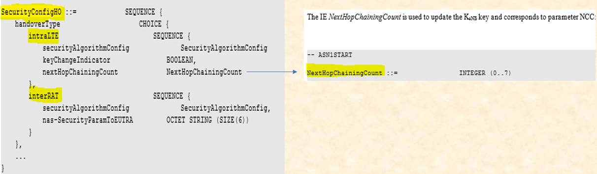
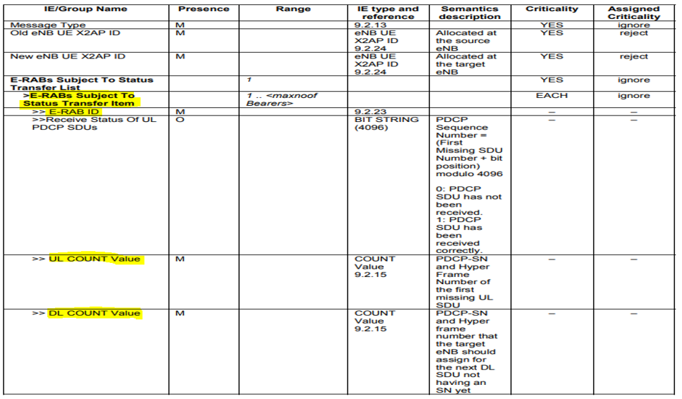
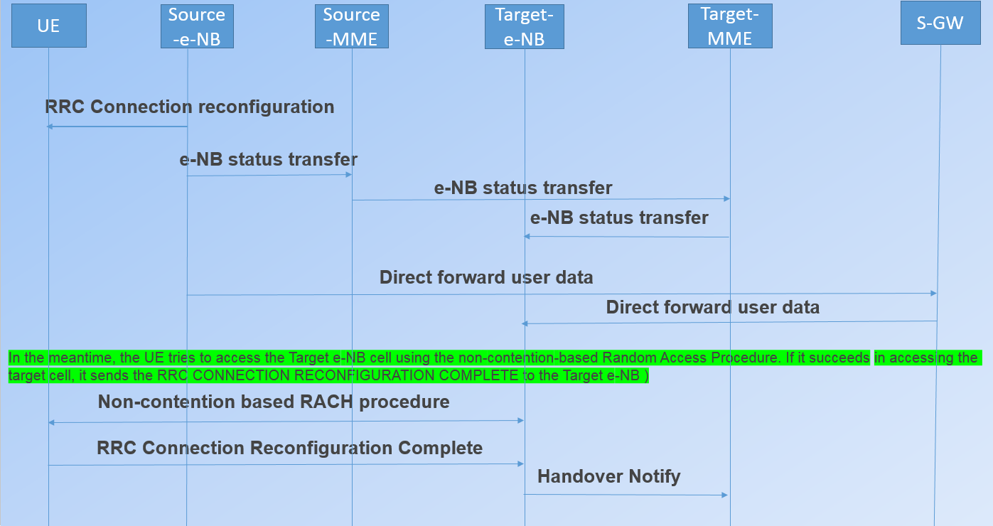
7. e-NB status transfer-
This message is sent by
the source e-NB to the target e-NB to transfer the uplink/downlink PDCP SN and
HFN status during a handover.
During HO execution
phase...Source e-NB sends Handover command (RRC Connection Reconfiguration
Command)to UE which instructs UE to detach from source e-NB. After that Source
e-NB sends "SN status Transfer message" (contains DL count and UL
count). UL count is count of first UL packet that is to be received by Target
e-NB from UE. DL count is count of first DL packet that is to be received by UE
from Target e-NB.
The Source e-NB starts
forwarding the downlink data packets to the Target e-NB for all the data
bearers (which are being established in the Target e-NB during the HANDOVER REQ
message processing).
In the meantime, the UE tries to access the Target e-NB cell using the
non-contention-based Random Access Procedure. If it succeeds in accessing the
target cell, it sends the RRC CONNECTION RECONFIGURATION COMPLETE to the Target
e-NB.8. RRC Connection Reconfiguration Complete –

9. Path Switch Request :-
The Target e-NB sends a
PATH SWITCH REQUEST message to the MME to inform it that the UE has changed
cells, including the TAI+ECGI of the target. The MME determines that the SGW
can continue to serve the UE.

10. Modify Bearer Request -
The MME sends a MODIFY
BEARER REQUEST (e-NB address and TEIDs for downlink user plane for the accepted
EPS bearers) message to the SGW. If the PDN GW requested the UE’s location
info, the MME also includes the User Location Information IE in this message.


10. Modify Bearer Response -


X2 handover (with S-GW change):
X2 handover when S-GW relocation:

Call Flow:


S1 handover (Without changing S-GW) :


Inter RAT HO (E-UTRAN-4G to UTRAN-3G) :


Preparation Phase:
In the Preparation phase,
resources are reserved in the target network. In the Execution phase, the UE is
handed over to the target network from the source network. The Preparation
phase message flow is given in Figure , followed by the description.
1.Once the inter-RAT
handover is decided at the Source e-NB based on the measurement report
procedure, it prepares and sends a HANDOVER REQUIRED message to the S-MME.
2. The S-MME detects that
it is an Inter-RAT handover from the message contents, retrieves the target
SGSN details from the database based on the information in the message. It now
prepares and sends a GTP-C: FORAWRD RELOCATION REQUEST to the T-SGSN.
3. The T-SGSN detects the
change of SGW and creates the bearer resources in the T-SGW by initiating the
GTP: CREATE SESSION procedure.
4. Once the resources are
reserved at the T-SGW, it responds to the T-SGSN with a GTP: CREATE SESSION
RESPONSE message.
5. The T-SGSN now reserves
the resources at the T-RNC by sending a RANAP: RELOCATION REQUEST message to
it.
6. The T-RNC reserves the
radio resources and responds to the T-SGSN with a RANAP: RELOCATION REQUEST ACK
message.
7. The T-SGSN creates the
indirect data forwarding tunnels in the T-SGW for the DL packets transfer from the S-SGW to T-SGW during the
handover.
8. After the Indirect Data
forwarding tunnel creation, the T-SGSN responds with a GTP: FORWARD RELOCATION
RESPONSE message to the S-MME.
9. The S-MME has to create
the indirect data forwarding tunnels as the resources are reserved successfully
in the target network to forward the DL packets to the target network. With
this, the preparation phase is complete.
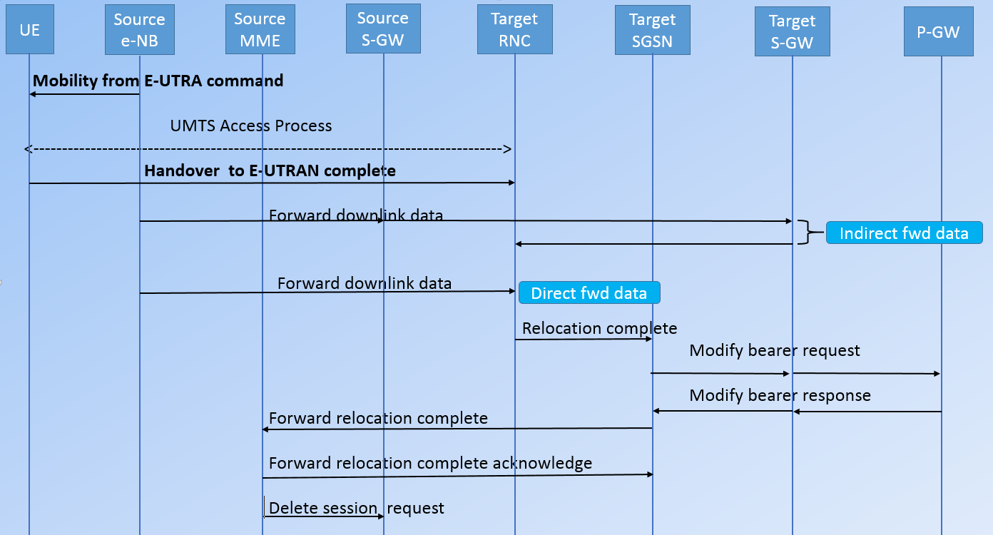
Execution Phase:
1. The Source MME sends
the HANDOVER COMMAND message to the Source e-NB with the target to source
transparent container (i.e., it has the reserved resource information at the
target).
2. The Source e-NB
prepares and sends the MOBILITY FROM EUTRA COMMAND message to prepare the UE
for the handover toward the target network.
3. After accessing the
target UMTS cell, the UE sends a HO TO UTRAN COMPLETE message to the T-RNC
signalling the successful handover.
4. The Source e-NB
forwards the DL data packets toward the T-SGW via the Source S-GW during the
handover. This step can happen any time after it receives the S1AP HANDOVER
COMMAND message from the S-MME. This
step is executed in case a direct forwarding path is not available with the
T-RNC, otherwise it will forward the DL data packets to the T-RNC directly.
Both the options are shown in below figure.
5. Once the T-RNC detects
the UE in its area, it notifies the T-SGSN about the completion of the handover
by sending a RANAP: RELOCATION COMPLETE message.
6. The T-SGSN notifies the
completion of handover to the S-MME by sending a GTP: FORWARD RELOCATION
COMPLETE NOTIFICATION ACK message. The S-MME acknowledges this message and
proceeds with release of the resources associated with this UE at the Source
S-GW and Source e-NB.
7. The T-SGSN modifies the
E-RAB resources at the T-SGW by initiating the GTP MODIFY BEARER procedure.
8. The T-SGW notifies the
bearer parameters with the PGW by initiating the GTP MODIFY BEARER procedure.
Handover require (Source e-NB ---> Source MME):
-S1AP Cause,
-Target RNC Identifier,
-CSG ID,
-CSG Access mode,
-Source e-NB Identifier,
-Source to Target
Transparent Container
When the target cell is a
CSG cell or a hybrid cell, the source e-NB shall include the CSG ID of the
target cell. If the target cell is a hybrid cell, the CSG access mode shall be
indicated.
Forward Relocation Request (Source MME---> Target
SGSN):
-IMSI,
-Target Identification,
-CSG ID,
-CSG Membership
Indication,
-MM Context,
-PDN Connections,
-MME Tunnel Endpoint
Identifier for Control Plane,
-MME IP Address for
Control plane,
-Source to Target
Transparent Container,
-RAN Cause,
-MS Info Change Reporting
Action (if available),
-CSG Information Reporting
Action (if available),
- UE Time Zone,
- ISR Supported (If indicated, the information ISR Activated
indicates that ISR is activated, which is only possible when the S GW is not
changed. When the Modify Bearer Request does not indicate ISR Activated and S
GW is not changed, the S GW deletes any ISR resources by sending a Delete
Bearer Request to the other CN node that has bearer resources on the S GW
reserved.)
This message includes all
PDN Connections active in the source system and for each PDN Connection
includes the associated APN, the address and the uplink Tunnel endpoint
parameters of the Serving GW for control plane, and a list of EPS Bearer
Contexts. RAN Cause indicates the S1AP Cause as received from source e-NB.
Create Session Request :
-
IMSI,
-
SGSN Tunnel Endpoint
Identifier for Control Plane,
-
SGSN Address for Control
plane, PDN GW address(es) for user plane,
-
PDN GW UL TEID(s) for user
plane,
-
PDN GW address(es) for
control plane and PDN GW TEID(s) for control plane,
-
Protocol Type over S5/S8,
Relocation Request :
-
UE Identifier,
- Cause,
- CN Domain Indicator,
- Integrity protection
information (i.e. IK and allowed Integrity Protection algorithms),
- Encryption information
(i.e. CK and allowed Ciphering algorithms),
- RAB (Radio Access Bearer)
to be setup list,
- CSG ID,
- CSG Membership Indication,
- Source RNC to Target RNC
Transparent Container,
- Service Handover related
information). If the Access Restriction is present in the MM context, the
Service Handover related information shall be included by the target SGSN for
the Relocation Request message in order for RNC to restrict the UE in connected
mode to handover to the RAT prohibited by the Access Restriction.
- For each RAB requested to
be established, RABs To Be Setup shall contain information such as RAB ID, RAB
parameters, Transport Layer Address, and Iu Transport Association. The RAB ID
information element contains the NSAPI value, and the RAB parameters
information element gives the QoS profile.
- The Transport Layer
Address is the Serving GW Address for user plane (if Direct Tunnel is used) or
the SGSN Address for user plane (if Direct Tunnel is not used), and the Iu
Transport Association corresponds to the uplink Tunnel Endpoint Identifier Data
in Serving GW or SGSN respectively.
- Ciphering and integrity
protection keys are sent to the target RNC to allow data transfer to continue
in the new RAT/mode target cell without requiring a new AKA (Authentication and
Key Agreement) procedure. Information that is required to be sent to the UE
(either in the Relocation Command message or after the handover completion
message) from RRC in the target RNC shall be included in the RRC message sent
from the target RNC to the UE via the transparent container.
- The Target SGSN shall
include the CSG ID and CSG Membership Indication when provided by the source
MME in the Forward Relocation Request message.
- In the target RNC radio
and Iu user plane resources are reserved for the accepted RABs.
- Cause indicates the RAN
Cause as received from source MME.
- The Source RNC to Target
RNC Transparent Container includes the value from the Source to Target
Transparent Container received from the source e-NB.
- If the target cell is a
CSG cell, the target RNC shall verify the CSG ID provided by the target SGSN,
and reject the handover with an appropriate cause if it does not match the CSG
ID for the target cell. If the target cell is in hybrid mode, the target RNC
may use the CSG Membership Indication to perform differentiated treatment for
CSG and non-CSG members.
- The target RNC allocates
the resources and returns the applicable parameters to the target SGSN in the
message Relocation Request Acknowledge (Target RNC to Source RNC Transparent
Container, RABs setup list, RABs failed to setup list).
- Upon sending the
Relocation Request Acknowledge message the target RNC shall be prepared to
receive downlink GTP PDUs from the Serving GW, or Target SGSN if Direct Tunnel
is not used, for the accepted RABs.
Each RABs setup list is defined by a Transport Layer Address, which is the target RNC Address for user data, and the Iu Transport Association, which corresponds to the downlink Tunnel Endpoint Identifier for user data.
Any EPS Bearer contexts for which a RAB was not established are maintained in the target SGSN and the UE. These EPS Bearer contexts shall be deactivated by the target SGSN via explicit SM procedures upon the completion of the routing area update (RAU) procedure.
Handover Command :
-Target to Source
Transparent Container,
- E-RABs to Release List,
- Bearers Subject to Data
Forwarding List).
The "Bearers Subject
to Data forwarding list" IE may be included in the message and it shall be
a list of 'Address(es) and TEID(s) for user traffic data forwarding' received
from target side in the preparation phase when 'Direct Forwarding' applies, or
the parameters received in Step 8a of the preparation phase when 'Indirect
Forwarding' applies.
The source e-NB initiates data forwarding for bearers specified in the "Bearers Subject to Data Forwarding List". The data forwarding may go directly to target RNC or alternatively go via the Serving GW if so decided by source MME and or/ target SGSN in the preparation phase.
The source e-NB initiates data forwarding for bearers specified in the "Bearers Subject to Data Forwarding List". The data forwarding may go directly to target RNC or alternatively go via the Serving GW if so decided by source MME and or/ target SGSN in the preparation phase.
HO from E-UTRAN Command :
The source e-NB will give
a command to the UE to handover to the target access network via the message HO
from E-UTRAN Command. This message includes a transparent container including
radio aspect parameters that the target RNC has set-up in the preparation
phase.
Upon the reception of the HO from E-UTRAN Command message containing the Handover Command message, the UE shall associate its bearer IDs to the respective RABs based on the relation with the NSAPI and shall suspend the uplink transmission of the user plane data.
Upon the reception of the HO from E-UTRAN Command message containing the Handover Command message, the UE shall associate its bearer IDs to the respective RABs based on the relation with the NSAPI and shall suspend the uplink transmission of the user plane data.
Inter RAT HO (UTRAN-3G to E-UTRAN-4G) :


In the Preparation phase,
resources are reserved in the target network, while in the execution phase the
UE is handed over to the target network from the source network.
Preparation phase:
1. Once the inter-RAT
handover is decided at the S-RNC based on the measurement report procedure, it
prepares and sends a RANAP RELOCATION REQUIRED message to the S-SGSN.
2. The S-SGSN detects that
it is an Inter-RAT handover from the message contents and retrieves the T-MME
details from the database based on the information in the message. It now
prepares and sends a GTP-C: FORAWRD RELOCATION REQUEST to the T-MME.
3. The T-MME detects the
change of SGW and creates the bearer resources in the T-SGW by initiating the
GTP: CREATE SESSION procedure.
4. Once the resources are
reserved at the T-SGW, it responds to the T-MME with a GTP: CREATE SESSION
RESPONSE message.
5. The T-MME now reserves
the resources at the T-eNB by sending aS1AP: HANDOVER REQUEST message to it.
6. The T-eNB reserves the
radio resources and responds to the T-MME with a S1AP: HANDOVER REQUEST ACK
message.
7. The T-MME creates the
indirect data forwarding tunnels in the T-SGW for the DL packets transfer from
the S-SGW to the T-SGW during the handover if there is no direct forwarding
path available from source to target.
8. After the Indirect Data
forwarding tunnel creation, the T-MME responds with a GTP: FORWARD RELOCATION
RESPONSE message to the S-SGSN.
9. The S-SGSN has to
create the indirect data forwarding tunnels, as the resources are reserved
successfully in the target network to forward the DL packets to the target
network. With this, the preparation phase is complete.
Execution Phase:
1. The S-SGSN sends the
RANAP RELOCATION COMMAND message to the S-RNC with the target to source
transparent container (it has the reserved resource information
at the target).
2. The S-RNC prepares and
sends the HO FROM UTRAN COMMAND message to prepare the UE for the handover
toward the target network.
3. After accessing the
T-eNB, the UE sends an RRC CONNECTION RECONFIGURATION COMPLETE message to the
T-eNB signaling the successful handover.
4. The S-RNC forwards the
DL data packets toward the T-SGW via the S-SGW during the handover. This step
can happen any time after it receives the RANAP RELOCATION COMMAND message from
the S-SGSN. This step is executed in case a direct forwarding path is not
available with the T-eNB, otherwise it will forward the DL data packets to the
T-eNB directly. Both the options are shown above in Figure .
5. Once the T-eNB detects
the UE in its area, it notifies the T-MME about the completion of the handover
by sending an S1AP: HANDOVER NOTIFY message.
6. The T-MME notifies the
completion of handover to the S-SGSN by sending a GTP: FORWARD RELOCATION
COMPLETE NOTIFICATION ACK message. The S-SGSN acknowledges this message and
proceeds with the release of the resources associated with this UE at the S-SGW
and S-RNC.
7. The T-MME modifies the
E-RAB resources at the T-SGW by initiating the GTP MODIFY BEARER procedure.
8. The T-SGW notifies the
bearer parameters with the PGW by initiating the GTP MODIFY BEARER procedure
CSFB (Circuit Switch Fallback) :
As we know there
is no CS present in LTE. So to make a voice call there are two solutions
available.
One solution:
In short CSFB is a procedure which LTE network redirect to legacy network 3G or 2G network to complete the voice call.
Second solution : is IMS based Vo-LTE call.
In Vo-LTE ,UE remains in LTE network to complete the voice call. But, whenever UE is not able to make Vo-LTE call because of some reasons such as UE is not capable or network does not support Vo-LTE, CSFB can take place to complete the voice call.

What are the pre-condition of CSFB ?
In short CSFB is a procedure which LTE network redirect to legacy network 3G or 2G network to complete the voice call.
Second solution : is IMS based Vo-LTE call.
In Vo-LTE ,UE remains in LTE network to complete the voice call. But, whenever UE is not able to make Vo-LTE call because of some reasons such as UE is not capable or network does not support Vo-LTE, CSFB can take place to complete the voice call.
What are the pre-condition of CSFB ?
1. UE and
network both should be support CSFB features
2. UE should send combined attached (Attach type: EPS/IMSI
attach) in attach request message. Means at the time of attach UE should attach
with LTE and legacy network 3G, 2G same time.
3. UE should be dual mode (4G and 3G) OR Triple mode (4G, 3G and 2G).
But for CSFB UE must be a dual mode
MO-CSFB call flow during data session is
ongoing / connected mode -
UE is already registered with the LTE and legacy network and data session is ongoing.
UE is already registered with the LTE and legacy network and data session is ongoing.
(AT Command: ATD:8369473218) or UE make a voice call during connected mode.

When UE receives this
message it tune into the target network.
In our example the target network is
UTRAN and UE will find a suitable cell and reads the MIB (Master Information Block) and other required System
Information Blocks(SIB1,3,5,7,11,12,19).
The next step is to start
the RRC connection procedure to initiate the voice call in UTRAN network.


Note: Two things will be possible here when data are ongoing in LTE network.
First- UE will suspend the data and move to UMTS network and established the voice call. After completing the call come back to LTE network and data gets resumed.
Second- All the information voice and data are transferred when UE moves to the UMTS network from LTE network.
MO-CSFB call flow when the UE is in idle mode -
UE has to move connected mode from idle mode by the establishment of RRC connection with the e-NB.

After this same process has been followed as in the above case (MO-CSFB call flow during data session is ongoing / connected mode).
MT-CSFB call flow during data session is ongoing / connected mode-
In case of MT call, our UE
is registered and is in LTE network. It receives a CS service notification EPS mobility management message for an
incoming call. The LTE network will redirect the UE to UMTS network to complete
the call.
CS Service Notification
message: This message is sent by the MME when a paging request with
CS call indicator was received via SGs for a UE, and a NAS signaling connection
is already established for the UE.
In response to this the UE
sends the Extend Service
Request message. In this message it mention the service type as “mobile terminating CS fallback”.
Also, it sets that the
CSFB request is accepted by the UE.
After receiving this
message, the UE prepares itself for CSFB procedure. It starts the timer T3417.
The e-NB then sends the "RRC Connection Release" with redirected carrier information which contains target RAT and frequency UARFCN(WCDMA) or ARFCN(GSM).

When UE receives this message it tune into the target network.
In our example the target network is UTRAN and UE will find a suitable cell and reads the MIB (Master Information Block) and other required System Information Blocks(SIB1,3,5,7,11,12,19).
The next step is to start the RRC connection procedure to initiate the voice call in UTRAN network.


Note: Two things will be possible here when data are ongoing in LTE network.
First- UE will suspend the data and move to UMTS network and established the voice call. After completing the call come back to LTE network and data gets resumed.
Second- All the information voice and data are transferred when UE moves to the UMTS network from LTE network.
MT-CSFB call flow when the UE is in idle mode -
After receiving paging message, UE has to move connected mode from idle mode by the establishment of RRC connection with the e-NB.

Note:
When UE is in the idle mode network will send paging messages, whereas in a connected mode network send CS service notification message to the UE.

The CSFB call setup failure rate and an overview of different reasons that may cause higher than expected failure rates as observed in live CSFB networks. The key associated issues have been categorized into three general areas: • Network Optimization • Network Configuration • Network Implementation In general, when driving along routes with the highest frequency of CSFB failures, initial CSFB to UMTS commercial deployments show up to 3 percent CSFB call setup failures. CSFB failures across the network are around 1–2 percent, which indicates the CSFB failure rate is close to that of legacy UMTS deployments.
Reasons for the call setup
failure :
The CSFB call setup failure rate and an overview of different reasons that may cause higher than expected failure rates as observed in live CSFB networks. The key associated issues have been categorized into three general areas: • Network Optimization • Network Configuration • Network Implementation In general, when driving along routes with the highest frequency of CSFB failures, initial CSFB to UMTS commercial deployments show up to 3 percent CSFB call setup failures. CSFB failures across the network are around 1–2 percent, which indicates the CSFB failure rate is close to that of legacy UMTS deployments.
NETWORK OPTIMIZATION RELATED CSFB
FAILURES :
1. CSFB calls involve
interaction between LTE and UMTS radio access and core networks. The lack of
suitable radio access planning, RF optimization and interference management or
poor interworking of both networks can lead to a variety of issues. Sub-optimal
UL LTE coverage (i.e., LTE planning) can lead to LTE Random Access Channel
(RACH) procedure failures. RACH failures may result in initial registration or
Tracking Area Update (TAU) failures. TAU failures can indirectly result in
missing pages for the duration the UE is not able to update its location. Poor
DL LTE coverage can also lead to paging failures. On the other hand, excessive
cell overlap can lead to excessive HO, both of which can result in CSFB call
failures. CSFB call setup failures are also observed due to UMTS optimization
related issues.
2. Blind redirection from LTE to UMTS is the most common mechanism in today’s CSFB deployments. Therefore, in areas of poor UMTS RF coverage or high load/interference, there is a risk CSFB call setup may encounter failures due to physical layer problems or failed RRC Connection procedures.
2. Blind redirection from LTE to UMTS is the most common mechanism in today’s CSFB deployments. Therefore, in areas of poor UMTS RF coverage or high load/interference, there is a risk CSFB call setup may encounter failures due to physical layer problems or failed RRC Connection procedures.
NETWORK CONFIGURATION RELATED CSFB
FAILURES :
Above lists some typical
cases where improper LTE/UMTS and core network configuration can lead to CSFB
call setup failures. Some LTE initial deployments do not have intra-frequency
measurements configured during TAU procedures. LTE measurements during TAU
procedures ensure that the UE completes a HO to the best cell immediately and
avoids MO/MT CSFB call setup failures.
3. In some initial deployments, LTE networks schedule SIB messages do not contain useful neighbor cell information (e.g. SIB4) [4]. In this scenario, while the UE waits to collect such LTE SIBs, and if sub-optimal RF conditions are encountered, this unnecessary delay may cause LTE cell reselection failures, which result in missed pages and MT CSFB call failures.
4. Inadequate UMTS CN configuration also impacts call setup performance. If the MSC timer (waiting for ESR after LTE page) is not properly set in relation to the DRX cycle setting in LTE, UEs may miss LTE pages, leading to failed MT CSFB calls. This is especially true when UEs are in suboptimal RF conditions and the MSC uses a large re-paging interval with a few retries. Setting the MSC Paging retry timer interval and count carefully based on the LTE Idle Mode DRX cycle is recommended.
NETWORK IMPLEMENTATION RELATED CSFB
FAILURES :
Above table lists some sub-optimal
network implementations and lack of certain feature support in LTE and UMTS
that can result in CSFB failures.
5. In mobility scenarios, CSFB call setup failures are a possibility during Intra-frequency handovers. In some of these scenarios, when HO execution is ongoing, CSFB issues might be observed due to MME implementation. In particular, if the MME receives a rejection to a UE Context Modification Request message with a CS Fallback indicator from the eNodeB with an indication that an X2/S1 handover is in progress, the MME shall resend the UE Context Modification Request with CS Fallback indicator to the target eNodeB. This ensures that the LTE RRC Connection Release message with redirection can be sent through the new cell when the HO is complete, or to the source eNodeB if the HO is deemed to have failed [3]. If the MME does not perform this action, CSFB establishment during HO execution is prone to failure.
6. Another issue in mobility conditions that leads to CSFB failures is associated with the network releasing the RRC connection before receiving an RLC ACK for the TAU complete message. This causes MT CSFB call setup failure because the MME cannot page the UE unless the TAU and LAU procedures are completed. Similarly, in UMTS, CS and PS domain Security Mode Command (SMC) procedure implementation can also lead to CSFB call setup failures when RLC ACK is not received for CS SMC before PS SMC is sent.
7. In general, eNodeBs and RNCs should provide sufficient delay to ensure receipt of RLC ACKs from UEs for prior signaling messages before sending any subsequent message. In some cases RNC implementations do not support Cell Update (CU) procedures for the CS domain, although they still enable a T314 timer for re-establishing a DCH (Dedicated Channel) in case of an RLF during the CSFB call setup procedure. Hence, the UE would initiate multiple Cell Update procedures (recovery technique) without receiving a confirmation, which significantly delays transmission of the RRC Connection Request. Support for such recovery procedures for CS calls can increase the probability of establishing a CSFB call in challenging RF conditions (especially in mobility).
8. When the UE is moving between multiple LA boundaries and across MSCs, poor interaction between the MME and MSCs can result in MT CSFB call setup failures. This could cause the target MSC to release the Iu-CS connection resulting in the UMTS network releasing the RRC connection, which eventually results in a CSFB call setup failure. Therefore, tight timing synchronization between the MSC and MME is required and precise handling of corner cases/race-conditions is needed.
Typically, in early
deployments, once network configuration and network implementation related
issues are addressed, network optimization related issues such as LTE RACH
failures, TAU failures, UMTS RRC Connection failures (coverage, congestion,
etc.) are commonly the cause of the CSFB call setup failures.5. In mobility scenarios, CSFB call setup failures are a possibility during Intra-frequency handovers. In some of these scenarios, when HO execution is ongoing, CSFB issues might be observed due to MME implementation. In particular, if the MME receives a rejection to a UE Context Modification Request message with a CS Fallback indicator from the eNodeB with an indication that an X2/S1 handover is in progress, the MME shall resend the UE Context Modification Request with CS Fallback indicator to the target eNodeB. This ensures that the LTE RRC Connection Release message with redirection can be sent through the new cell when the HO is complete, or to the source eNodeB if the HO is deemed to have failed [3]. If the MME does not perform this action, CSFB establishment during HO execution is prone to failure.
6. Another issue in mobility conditions that leads to CSFB failures is associated with the network releasing the RRC connection before receiving an RLC ACK for the TAU complete message. This causes MT CSFB call setup failure because the MME cannot page the UE unless the TAU and LAU procedures are completed. Similarly, in UMTS, CS and PS domain Security Mode Command (SMC) procedure implementation can also lead to CSFB call setup failures when RLC ACK is not received for CS SMC before PS SMC is sent.
7. In general, eNodeBs and RNCs should provide sufficient delay to ensure receipt of RLC ACKs from UEs for prior signaling messages before sending any subsequent message. In some cases RNC implementations do not support Cell Update (CU) procedures for the CS domain, although they still enable a T314 timer for re-establishing a DCH (Dedicated Channel) in case of an RLF during the CSFB call setup procedure. Hence, the UE would initiate multiple Cell Update procedures (recovery technique) without receiving a confirmation, which significantly delays transmission of the RRC Connection Request. Support for such recovery procedures for CS calls can increase the probability of establishing a CSFB call in challenging RF conditions (especially in mobility).
8. When the UE is moving between multiple LA boundaries and across MSCs, poor interaction between the MME and MSCs can result in MT CSFB call setup failures. This could cause the target MSC to release the Iu-CS connection resulting in the UMTS network releasing the RRC connection, which eventually results in a CSFB call setup failure. Therefore, tight timing synchronization between the MSC and MME is required and precise handling of corner cases/race-conditions is needed.
9. After released the call, the UE has to read SIB-19 and moved back to the LTE network and UE initiates a tracking area update after moving back to the LTE network.But in some cases where UE has failed to read SIB-19 and TA update
getting failed.
SRVCC (Single Radio Voice Call Continuity) :
HOW SRVCC WORKS:
SRVCC (Single Radio Voice Call Continuity) :
HOW SRVCC WORKS:
SRVCC solution is used
when the Vo-LTE call cannot be continue due to coverage holes/poor coverage
of LTE network. In such cases SRVCC allows a packet switch Vo-LTE call to transaction to a legacy circuit switch network. Its a basically handover of ongoing voice call from the IMS network to circuit switch legacy system such as 3G without dropping the call.
EVOLUTION OF VOICE CALL:
 Lets understand the evolution of a voice call .On the left hand side we can see it is a 2G legacy network. Voice call are made practically only on the circuits for each call on circuit switch domain. While we move to 3G its more or less similar to 2G networks, no major change other than supporting some advance codecs. Now, comes CSFB which is used in the operators where LTE have been launch without support of Vo-LTE services.
The next one is LTE network support Vo-LTE call. Next one is SRVCC extension where we allow handover of a call from LTE to 2G, 3G network in case there are coverage holes in the 4G network.
The last one is enhanced SRVCC and alerting SRVCC which reduces call switching time when the user moves from 4G to 3G or 2G Radio. This improves user experience to a greater extend.
Difference between CSFB and SRVCC :
 1. On the left hand side we can see it's a CSFB and on the right hand side we can see it's a Vo-LTE +SRVCC . Now, lets start with CSFB approach. CSFB is a circuit switch fallback. This is applicable to operators where LTE does not supported Vo-LTE for voice call (CS call). It uses legacy 2G/3G network for providing voice services to the users. There is SGs link between MME and MSC for handling incoming and outgoing call communication.
When user is trying to call, user goes to 3G network where he camped on RNC and can make or receives the calls. This is the temporary solutions and will eliminate over the times where all the operator upgrade the Vo-LTE services.
Now, lets discuss Vo-LTE + SRVCC which is there on the right hand side. SRVCC is single radio voice call continuity. SRVCC is a call transfer method or handover which implemented is a simplified and a reliable manner.
SRVCC is used when the Vo-LTE call can not be continue due to coverage holes /poor coverage of LTE network. In such cases SRVCC allows a packet switch Vo-LTE call to transaction to a legacy circuit switch network such as 3G/ 2G.
The main advantage is the call will not dropped. This is permanent solution and this is going to stay for a longer duration.
2. CSFB is a service based handover procedure where as SRVCC is a coverage based handover procedure based handover.
3. As compare with the CSFB, SRVCC is the more convenience and advance for the user experience.
4. When operator used the CSFB, the biggest problem or disadvantage is that the increase the call setup time due to retuning procedures required for 2G/3G Radio. Where as Vo-LTE provide the faster call setup time.
5. The call quality in Vo-LTE is better to specific QOS allocated to the IMS call and the codec which have been used in Vo-LTE and IMS, they are far superior than legacy network. They can provide better quality which is not than in the 2G or 3G legacy network.
6. Resource benefit for Vo-LTE :
Codec used in Vo-LTE require much less resource and it consumes much lower data rate as compared to CSFB which working on 2G or 3G network using a dedicated circuits.
Evolution of SRVCC :-
Name 3GPP Description
Basic
SRVCC Rel-8 Call continuity from e-UTRAN &UTRAN/GERAN.
a SRVCC Rel-10 Packet switch to circuit switch call transfer during
altering phase.
e SRVCC Rel-10 Enhance SRVCC (support for MSC server assisted
mid call feature )
v SRVCC Rel-11 Video SRVCC
r SRVCC Rel-11 SRVCC from UTRAN/GERAN to E-UTRAN.
SRVCC call flow:-

Here, we are going to
discuss about procedure of how SRVCC works.
In these case we will take example for an operation. Assuming that both packet switch and voice are running on LTE and what could happened if UE goes on bad coverage of LTE and how SRVCC is going to transfer the call from LTE towards UMTS.
Just like in handover there are two phase. In this case we divided Phase1 and Phase2.
So, the first phase about the setting up of the preparation requirement meaning report actual session transfer take place voice and data. What should be the signalling requirement in terms of back end. Front end need to take place for the actual session transfer. So, this will done in phase1 and actual session transfer and session deletion take place in phase2.

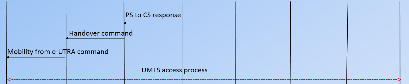


Carrier Aggregation can be used for both FDD and TDD.So, when there is no CA , we will receives and transmits the data on a single carrier. This carrier is called Primary Component Carrier(PCC) and
corresponding cell is called Primary Serving Cell.
In case sub-carrier aggregation one or more sub-carrier /carrier components are aggregated with primary component carrier in order to support wider transmission bandwidth.
Primary component carrier from primary serving cell remains the air. Only secondary component carrier from secondary serving cell are added or deleted.
What is the role played by primary component carrier(PCC) in CA :
1. It adds or removes secondary component carriers dynamically based on measurement report received on UE.
2. It dynamically activates and deactivates secondary cells.
3. It handles all the RRC and NAS procedures.
4. It receives measurement reports and controls mobility of UE.
5. Primary cell can be changed only at the time of handover.
Secondary Component Carrier (SCC):
1. As per Release-10, UE can aggregate maximum upto 5 carrier i.e 1 PCC and 4 SCC.
2. Maximum bandwidth that can be allocated to an UE is 100Mhz (20+20+20+20+20).
3. Actual number of SCC that can be allocated to an UE depends on UE capabilities.
4. It is not possible to configure on UE with more uplink CCs than downlink CCs but reverse can be true.

Types of LTE Carrier Aggregation:
There are a number of ways in which LTE carries can be aggregated-
1. Intra band,contiguous.
2. Intra band, non-contiguous
3. Inter band, non-contiguous
1. Intra band,Contiguous :
 The Intra band scenario provide benefit in term of implementation effort. A single transceivers can
In this schemes, primary component carrier and secondary component carriers are allocated the same band but they are non- contiguous (Means they have gap between them ).
3. Inter-band non-contiguous :
The inter-band scenario provides benefit in terms of spectrum availability.An operator's spectrum is likely to the distributed across multiple operating band rather than located within single band.
Denotes: CA_X-Y (e.g - CA_5-8).
There are almost 50 LTE bands available as per latest specifications. So there will be infinite number of possible band combinations if we use all the carrier allocation schemes.

EVOLUTION OF VOICE CALL:
The next one is LTE network support Vo-LTE call. Next one is SRVCC extension where we allow handover of a call from LTE to 2G, 3G network in case there are coverage holes in the 4G network.
The last one is enhanced SRVCC and alerting SRVCC which reduces call switching time when the user moves from 4G to 3G or 2G Radio. This improves user experience to a greater extend.
Difference between CSFB and SRVCC :
When user is trying to call, user goes to 3G network where he camped on RNC and can make or receives the calls. This is the temporary solutions and will eliminate over the times where all the operator upgrade the Vo-LTE services.
Now, lets discuss Vo-LTE + SRVCC which is there on the right hand side. SRVCC is single radio voice call continuity. SRVCC is a call transfer method or handover which implemented is a simplified and a reliable manner.
SRVCC is used when the Vo-LTE call can not be continue due to coverage holes /poor coverage of LTE network. In such cases SRVCC allows a packet switch Vo-LTE call to transaction to a legacy circuit switch network such as 3G/ 2G.
The main advantage is the call will not dropped. This is permanent solution and this is going to stay for a longer duration.
2. CSFB is a service based handover procedure where as SRVCC is a coverage based handover procedure based handover.
3. As compare with the CSFB, SRVCC is the more convenience and advance for the user experience.
4. When operator used the CSFB, the biggest problem or disadvantage is that the increase the call setup time due to retuning procedures required for 2G/3G Radio. Where as Vo-LTE provide the faster call setup time.
5. The call quality in Vo-LTE is better to specific QOS allocated to the IMS call and the codec which have been used in Vo-LTE and IMS, they are far superior than legacy network. They can provide better quality which is not than in the 2G or 3G legacy network.
6. Resource benefit for Vo-LTE :
Codec used in Vo-LTE require much less resource and it consumes much lower data rate as compared to CSFB which working on 2G or 3G network using a dedicated circuits.
a SRVCC Rel-10 Packet switch to circuit switch call transfer during
altering phase.
e SRVCC Rel-10 Enhance SRVCC (support for MSC server assisted
mid call feature )
v SRVCC Rel-11 Video SRVCC
r SRVCC Rel-11 SRVCC from UTRAN/GERAN to E-UTRAN.
In these case we will take example for an operation. Assuming that both packet switch and voice are running on LTE and what could happened if UE goes on bad coverage of LTE and how SRVCC is going to transfer the call from LTE towards UMTS.
Just like in handover there are two phase. In this case we divided Phase1 and Phase2.
So, the first phase about the setting up of the preparation requirement meaning report actual session transfer take place voice and data. What should be the signalling requirement in terms of back end. Front end need to take place for the actual session transfer. So, this will done in phase1 and actual session transfer and session deletion take place in phase2.
First thing ,we need to
understand as we know handover in LTE they needs be any events to take
place(A3,A5).
-e-NB asking for the
measurement report in 'RRC connection reconfiguration’ message to the UE and UE
sends the 'measurement report' to the e-NB.
Once the measurement
report is received its upto the e-NB to decide either handover decision meaning
H.O is take place or not.
In this case serving e-NB
knows the coverage is going to bad for the user .Then upto his decision that
handover procedure need to take place or not.
Assuming, Let say e-NB
decides SRVCC procedure need to take place and it has to identify the target
RNC and the nodeB where UE will eventually go into handover.
And we are assuming this
is case, e-NB sends the 'handover require' message to the MME using S1AP
protocol over S1-MME interface. This message contains Handover type - SRVCC is
going to use in UMTS, Target ID of RNC, Location area identity, SRVCC Handover
type - Either PS or CS or Both PS+CS.
In this case ,Assuming
SRVCC Handover type - Both PS+CS.
Once this particular
message is received by the MME, it going to divide or split that message in to
two portion- packet switch and circuit switch.
In this case, MME has to
send the required portion or request towards the respective parties. For
circuit switch MME will forward the request to the Media Gateway (MGW)to MSC
server and it will send this request as PS to CS request to MGW and it is going
forward the same request in prepare for Handover message towards target MSC.
Now target MSC going to ask the target RNC meaning to find out if target RNC is
ready to take the handover request or not.
Let us say target RNC does
agree to it to this relocation request ,then it is going to send the
acknowledgment ,However before that particular request acknowledgment happens.
As we know our original request consist of data and voice portion both.
So for data portion MME
will forward the forward relocation request towards the SGSN. Once this is
received by SGSN, he will forward the relocation request once again towards the
target RNC. Now target RNC is going make the decision for both the request PS
and CS and he will send the response towards both SGSN and MSC that is
Relocation ACK. and this forward relocation response is going back to MME.
In circuit switch portion
,Once Target MSC received this information, he will back to response that is
prepare handover response towards MGW. Means circuit has been established here.
Now ,before this responses forward to MME ,MGW has to inform the IMS server as
well. So that IMS can get ready to transfer his session. Meaning IMS has
transfer the session from LTE to UMTS .Once this request (Initialization of
session transfer) is sent then MGW sending response(PS to CS response) towards
the MME. which is for initial response . Once MME Receives this
information/response, he will send the 'Handover Command" towards e-NB and
e-NB sends ‘Mobility from EUTRA command' towards UE. The simply meaning
is UE should move to UMTS network and get it tuned to the network.
Now, what about the IMS,
meantime IMS is getting ready to transfer the session and also it is getting ready
to release the IMS access leg for the session which is running from LTE and
transfer the session into the UMTS side .
that is Phase-1
In phase 2,UE is going to
tunes towards the UMTS and once it gets tuned, the target RNC is going to
inform to MSC that relocation has been detected in 'Relocation Detect' message.
Once Relocation has been detected the target RNC going to inform same message
to SGSN in 'relocation detect' message and then handover complete take placed
towards the target RNC which simply indicates the handover of the UE towards
RNC is completed in 'Handover to UE complete' message.
Then, Target RNC is going
to send the response towards MSC that is 'Relocation complete' and then MSC is
forward this towards MGW indicating handover has been completed that is HO
complete.
Once MGW received this
message ,then he inform to MME that PS to CS has been completed in PS to
CS complete notification message and MME responses PS to CS
complete ACK to MGW .
Now ,MME delete the bearer
voice session which was going through .Now we have the packet switch as well as
circuit switch meaning is voice and data bearer will be deleted.Now
we still have the packet session switch meaning is data bearer. So for
that MME will send the forward Relocation Complete Acknowledgement.
But before sending the
Forward relocation complete acknowledgement Target RNC informs to SGSN that
Relocation has been completed in RELOCATION complete message.
And SGSN will talk to
Target SGW for modify the bearer and once bearer has been modified. SGSN
responded FORWARD Relocation complete message towards MME and MME responded for
that Forwarded Relocation complete ACK.
Then MME delete the
session for PS(delete session) as well as UE context.
Now, UE is in connected
with UTRAN/UMTS. So this is how SRVCC seamlessly UE is handed over from LTE
towards 2G or 3G for voice session and packet session together being transfer
depending on what feature we are using.
Carrier Aggregation (CA) :
Carrier Aggregation (CA) :
What is Carrier Aggregation :
Carrier Aggregation can be used for both FDD and TDD.So, when there is no CA , we will receives and transmits the data on a single carrier. This carrier is called Primary Component Carrier(PCC) and
corresponding cell is called Primary Serving Cell.
In case sub-carrier aggregation one or more sub-carrier /carrier components are aggregated with primary component carrier in order to support wider transmission bandwidth.
Primary component carrier from primary serving cell remains the air. Only secondary component carrier from secondary serving cell are added or deleted.
What is the role played by primary component carrier(PCC) in CA :
1. It adds or removes secondary component carriers dynamically based on measurement report received on UE.
2. It dynamically activates and deactivates secondary cells.
3. It handles all the RRC and NAS procedures.
4. It receives measurement reports and controls mobility of UE.
5. Primary cell can be changed only at the time of handover.
Secondary Component Carrier (SCC):
1. As per Release-10, UE can aggregate maximum upto 5 carrier i.e 1 PCC and 4 SCC.
2. Maximum bandwidth that can be allocated to an UE is 100Mhz (20+20+20+20+20).
3. Actual number of SCC that can be allocated to an UE depends on UE capabilities.
4. It is not possible to configure on UE with more uplink CCs than downlink CCs but reverse can be true.
Types of LTE Carrier Aggregation:
There are a number of ways in which LTE carries can be aggregated-
1. Intra band,contiguous.
2. Intra band, non-contiguous
3. Inter band, non-contiguous
1. Intra band,Contiguous :
The Intra band scenario provide benefit in term of implementation effort. A single transceivers can
transmit and receive multiples RF carrier when they are positioned within the same operating band.
Denotes: CA_X (e.g CA_5) In this schemes, primary component carrier and secondary component carriers are allocated the same band but they are non- contiguous (Means they have gap between them ).
3. Inter-band non-contiguous :
The inter-band scenario provides benefit in terms of spectrum availability.An operator's spectrum is likely to the distributed across multiple operating band rather than located within single band.
Denotes: CA_X-Y (e.g - CA_5-8).
There are almost 50 LTE bands available as per latest specifications. So there will be infinite number of possible band combinations if we use all the carrier allocation schemes.
RRC Connection Re-establishment.
Please refer my note .
Please refer my note .
Note: UE RRC Constructs this message and passes it to lower layers for transmission. Here, Random Access Procedure will be triggered to send the RRC Connection Reestablishment message. Note that the contention resolution of the RA procedure will be PDCCH order based on C-RNTI.
PDCCH Order in LTE
PDCCH Order is a procedure to bring back uplink out-of-sync UE (user equipment) back to in-sync state incase there is downlink data available for it. This can happen in situation when the time alignment Timer gets expired because there is no uplink and dowlink data transmission for some time and also when there is no Time alignment command recieved from eNB. Time Alignment timer basically controls how long the UE is considered uplink time aligned.
For viewers to better understand PDCCH Order, here is an example :
For viewers to better understand PDCCH Order, here is an example :

- Lets assume we have a UE that is in RRC connected state
- There is uplink / downlink user data being transmitted for some time (like facebook activity etc)
- There is no more data to be transmitted. Time Alignment timer will start (expiry setting = 10 seconds). But remember the RRC Inactivity Timer will also start since there is no data activity but lets assume that our Inactivity Timer doesnt expire and we remain in RRC connected state for whole duration
- Time Alignment timer expires and UE is considered uplink out-of-sync now. At this point UE releases all PUCCH (scheduling resources, CQI configuration) and SRS resources. UE also flushes its HARQ buffers
- UE is still in RRC Connected state but it has no PUCCH/SRS resources as they were released previously. Now there is DL data in eNB buffer for UE (Like facebook notification or something) but first UE has to be brought back to in-sync state and also it needs to reconfigured again with PUCCH/SRS resources
- eNB sends PDCCH order to UE using DCI 1A format. This is basically signal to UE to perform the contention less RACH with preamble index already included in DCI 1A
- UE sends MSG1 using RACH preamble acquired from PDCCH order (To read more about RACH procedure in LTE, click here)
- eNB sends RACH response with new time advance value so that UE can be uplink in-sync
- UE is in sync again !
- Next eNB sends RrcConnectionReconfiguration message which carries PUCCH/SRS as they were released when the time alignment timer was expired at step 4
- UE confirms reception of RrcConnectionReconfiguration message and now can resume uplink/downlink transmission of data
Why UE needs time alignment ?
Due to different signal transmission paths and movement, UE can lose time synchronization to eNB subframe. eNB measures the time alignment of UE by measuring the difference between arrival time of PUCCH, PUSCH, SRS to its own uplink subframe
More information pending to be updated
RRC
 Reviewed by LTE/IMS reference
on
March 23, 2018
Rating:
Reviewed by LTE/IMS reference
on
March 23, 2018
Rating:
Reviewed by LTE/IMS reference
on
March 23, 2018
Rating:

No comments: