
Basic LTE
Attach Procedure
1. Each UE that is attached to the LTE
network has at least one bearer available,that
is called default bearer.
is called default bearer.
2. Its goal is to provide continuous
IP connectivity towards the EPC (“ Always ON concept”)
3. From the Qos
point of view, the default bearer is normally a quite basic bearer.
4. If a specific service requires more
strength Qos attributes, then a dedicated bearer
should be established.

Normally 1 per PDN. That means if
mobile equipment by default is connected to 5 PDNs,
then 5 default bearers
will be created.
One
for each PDN. Normally only one.
Now, if mobile equipment is
connected to all the 5 PDNs initially at the time of attach, E-NB
tell to MME
that mobile equip. want to connect to
all the 5 PDNs, so MME talk to
corresponding PDN gateways which are connected
to this PDNs and will have to create 5
EPS default bearer at the time of
attach. Assume that these 5 PDN are connected to 5
different PDN gateways. Each
PDN gateway will have one IP address to mobile phone.
From PDN gateway to SGW 5
tunnels will be created. But irrespectively of that how many
PDNs a mobile
equip. is connected to, he must be connected to only one SGW. That
means single
SGW mobile equip. is connected to 5 PDN gateway and 5 tunnels (S5/S8
bearers)
will be created between SGW and PGW.
So ,After E-RAB establishment
mobile equipment will have 5 IP address, 5 Radio bearers,
5 S1 bearers and 5
S5/S8 bearers and will be connected to 5 PDNs.
With these 5 existing RABs mobile
equip. can actually send data to any application server
present in any 5
PDNs.
Now assume that suddenly one of
the packet
data network
started
with
very high
data rate
call. That means default bearer is not enough, so dedicated EPS
bearer needs
to
be
created. While
creating a
dedicated bearer,
we need
to create one more tunnel b/w PGW
to SGW (s5/s8 bearer) and SGW to E-NB (s1 bearer).
E-NB to
mobile equip.
we need
to create 6th Radio bearer which is having different Qos
than the existing Radio bearers
(so, mobile equip. knows by RRC
Connection
Reconfiguration
message
send by E-NB).
Now at the time of initial context
setup request default bearer will be created but later if
dedicated bearer is getting created then
MME will send to E-NB that is E-RAB
setup
and
after that E-NB will send same info. to mobile equipment in RRC Connection
Reconfiguration message.
When
many default
bearers are created-
First scenario-
If mobile equip. wants
to
connect 3 different packet data network like
IMS,INTERNET,
VPN. 3 default bearers
need
to be created even though Qos is same because there is
possibility that these three PDN can be connected to three
different PDN gateways.
Second Scenario-
If mobile equip. wants
to
connect only one PDN like internet, but if
10
applications are
running,
out of these 10 applications 8 are same Qos and 2 are same Qos.
Then we need 2
default bearers even though only
one PDN
gateway is
required.
So, Bearer concept
depend on 2 things- one is Qos and
other is PDN gateway.
Dedicated can be one or more on
high Qos
basis.
EPS
bearer Qos
Attributes –
For every EPS bearer we must have
below parameters -
ØTo
be define per bearer
-Default / Dedicated bearer
- GBR/ N-GBR
- MBR
-UL/DL TFT(It is just like a port no. through
which we can send the data corresponding
application of same EPS bearer or
different EPS bearer.)
-QCI
- ARP
(How long retain the bearer setup.
ØTo
be define per User
- AMBR
QCI
(Quality of service class identifier ) –
Every EPS bearer will have a QCI.
One of the 9 QCI
depending on
what application we
use.

Attach
procedure for the user-

The very first
time when mobile equipment is switched ON, mobile equipment is in
EMM_Deregistered State.
EMM_Deregistered State.
1. Once
UE is switched
ON
2. PLMN search operation starts
3.UE NAS layer reads HPLMN information and frequency band gives it to RRC layer and
asks RRC to find the PLMN.
2. PLMN search operation starts
3.UE NAS layer reads HPLMN information and frequency band gives it to RRC layer and
asks RRC to find the PLMN.
4. RRC
takes the help from physical layer to synchronize with different cells in the
frequency band and read PLMN id.
5. RRC reports success to NAS if it finds the HPLMN.
6. NAS orders latching on to one of the cells in that PLMN.
7. RRC with the help of physical layer decides a cell to latch on
5. RRC reports success to NAS if it finds the HPLMN.
6. NAS orders latching on to one of the cells in that PLMN.
7. RRC with the help of physical layer decides a cell to latch on
based on signal strength comparison.
8. UE
must
perform sync with selected cell.
........Cell Synchronization and Registration
.............
ØUE
should read PSS (primary synchronization
signal ) to find sector Id (0,1,2)
ØUE
should read SSS (Secondary
synchronization signal ) to find Group Id (0- 167)
ØUE
calculate PCI with 3*Group Id + Sector Id. synchronization.
[ As
soon as UE switches ON the first duty is synchronization.
For synchronization
we have two channels, one is PSS and the other one is SSS.
So,
by reading primary synchronization signal mobile will have sector
id (0,1,2). Similarly by
reading the secondary synchronization
signal mobile find Group id (0-167).
Once
the mobile find these two factors: sector id
and group id, then mobile can find out PCI
(Physical cell id).

PCI has got a formula that is-
PCI = 3* Group id + Sector id.
The PCI range is 0 to 503. Total 504 physical
cell id . This cell is repeating to neighbor cell,
it may be
repeating to far way cell. PCI is very much important in order to download
broadcasting data because all the broadcasting data and
rest of the information will
be
transmitted to the mobile
equipment by using PCI only because if we wont do that the
broadcasting info. of this cell and broadcasting info. of next
cell will be merged. Whenever
we will try to read the broadcasting channel, we
will get the broadcasting channel data
which is a mixed information of this cell and the next cell. We don’t want that, so for
all the
information's that are
getting transmitted we must use
PCI. Even in LTE we use same
frequency in neighbor
cell also. So in order to separate the frequency from one
single
antenna, we must use PCI. PSS and SSS are
always present in middle PRBs. PSS and
SSS are always transmitted on
the air by using the central 72 carriers/ central frequency
sub carriers always.
So, once we find out PCI, we need to do some
kind of verification for the PCI.
Verification
can be performed by a special signal called a Reference signal
(RS). This RS is used for
verification of PCI. Many reference signals
are available in LTE frame architecture , So this
reference signal finds
out what is the interference effect on LTE system ]
Ø Verify PCI
against the PCI found in reference signal.
ØNow UE’s physical layer reads the
information PBCH.
In PBCH
MIB information is present . Actually
UE read to MIB to get the Bandwidth
(n6,n15, n25, n50, n100), PHICH and system frame number (SFN). SFN is very much
important to read SIB1. SIB1 will be present only in SFN
mod 8=0 sub frame no.5. Actually
MIB is the RRC information. PHY
layer won’t understand what is Band, what is SFN. PHY
layer just reads
it but the info. is forwarded to
MAC, MAC will forward to RLC, RLC will
forward to
RRC. So finally RRC is the one who reads this information. So RRC get the
MIB
info and he got to know what is the SFN. He
will tell to PHY layer when to read the data
again. Next is read
SIB1. SIB1 finds out the channel called PDSCH. But in order to read the
SIB1 info.we must be able to read a channel called
as PDCCH. PDCCH gives which
subcarrier
is allocated for SI-RNTI. But in
order to read PDCCH there are two
other crucial
steps because UE need to understand how many symbols are
reserved for PDCCH as
PDCCH is not fixed. It is variable depending on the traffic (users). So, how
many symbols
are reserved for PDCCH that information will be given by PCFICH. From the PCFICH UE
will get how many symbols are reserved for
PDCCH But problem is PCFICH is also not
in
a constant position. So RRC layer find out where the PCFICH slots are and he
will give
information to PHY layer and tell him that in next radio frame you will have to read
PCFICH.
ØUE
RRC calculates which position and
symbols are used for PCFICH
because PCFICH also dependent on PCI and Bandwidth. So UE
RRC asks PHY layer to
read corresponding
symbols in next radio frame,sub frame0 , slot 0. first symbol.
ØUE gets information how many symbols are reserved for PDCCH channel.
ØUE
reads PDCCH channel in sub frame no.5 of
SFN mod 8=0 and understand which
resources are allocated for SI-RNTI.
ØUE
should read SIB1 [ In PDCCH ]- SFN mod 8=0 sub frame #5.
ØUE
decode the information received on PRB
indicated for SIB1. Once UE decodes
PLMN ID, Tracking Area
Code, Cell id cell barred, periodicity of other SIBS (SIB2
SIB12………rf3, rf16,
rf32, rf64 …..etc)
ØRRC
gets to know the scheduling information for different SIBs. RRC provides this
information to PHY layer to read all the 12 SIBs.
ØBy
following the scheduling information for SIBs, UE reads all the SIBs.
So, once UE reads all the 12 SIBs, first duty of UE is over. The first duty is to acquire all the
system
information which is essential for all of his tasks.UE
has successfully synchronized
and read full system
information.But at this stage UE is still
EMM _ Deregistered State .
From
SIB1 UE acquire uplink channels like
which PRB is allocated for PRACH,
which
PRB is allocated for PUSCH, which PRB is allocated for PUCCH. UE knows by
reading all
the system information.
------Next
job of UE is
to perform Registration with MME----------
To do the registration, first UE
should make a connection with E-NB.
ØNAS
layer asks UE’s RRC layer to make a connection with E-NB.
ØRRC
makes a message called RRC Connection Request.
This message would come
to RLC, RLC will be pumping it to MAC.
Now
MAC
will send it to E-NB with the help of PHY layer. So, out of these uplink channel UE
should use PUSCH channel for
sending the RRC Connection Request. In LTE we wont
make RRC Connection for resources. It is just connection
making. Resource acquiring is
the
job of MAC layer. That means RRC connection request message is
waiting here and
UE will acquire the resource by performing Random Access
Procedure (RACH). As soon
as the UE get resource from E-NB, then UE
will send this request to E-NB.
ØSo,
RRC message is waiting in MAC layer buffer until RACH is performed.
-------------RACH
procedure to acquire uplink Resources---------------
There are two types of RACH
1. Contention
Based (
User don’t have any ID , is use at initial time)
2. Non-Contention Based (User having ID, is use for handover )
2. Non-Contention Based (User having ID, is use for handover )
Contention Based RACH procedure
Ø
UE
has a list of 64 preambles stored
ØMAC
layer picks randomly
one preamble
ØMAC
gives physical layer this preamble data to be sent out in PRACH symbols
ØBased
on sub-frame and slot of PRACH used,
UE’s physical layer calculate RA-RNTI.
RA-RNTI means Random Access-
RNTI. Why RA-RNTI is used ?
Every user have own RA-RNTI. So by using
different RA-RNTI E-N decides which user is
used for which RA-RNTI for sending the resource on PDSCH channel.
RA-RNTI = 1+ t _id + 10 * f _id
t_id
= is the index of the first sub frame of the specified
PRACH (0 < t_id <10 )
f_id = is
the index of the specified PRACH with in that
sub-frame. (0 < f_id <10
)
After sending this preamble information
what UE will do? UE will keep monitoring PDCCH
channel and expecting that there
is data getting in PDSCH channel in so on so
PRB and in
so on so sub carrier.
ØE-NB
also
calculate the RA-RNTI and allocates the resources to UE and need to send
this information to UE by using
PDSCH channel as an Random Access Response (RAR)
E-NB
will send RAR by using RA-RNTI .
RAR = [ 1 Reserved bit + 11 bit Timing
Advance Command + 20 bit uplink grant + 16 bit T
CRNTI ]
ØE-NB
modulates
this information on PDSCH and scheduling details are attached
to PDCCH by using RA-RNTI.
ØUE
PHY layer reads this information (RAR) and forward to MAC.
ØNow
UEs MAC layer sends the data (RRC connection req./ msg3) to PHY layer
by using allocated resource and send it
to E-NB by using T-CRNTI on PUSCH. Now UE
start with contention resolution
timer. with in the timer if E-NB have to confirmed to UE by
using UE contention
resolution identity / msg4 (S-TMSI / Random value). That means UE
definitely
will get RRC connection setup message from E-NB.
ØE-NB
RRC receives this information (msg3) and he prepares RRC Connection
Setup. So this setup message comes
from RRC --à
RLC --à
MAC. Now MAC needs to
send it out.
ØMAC
allocates PRB for UE to send this RRC message scheduling
to be send to UE on
PDCCH by using T-CRNTI.
ØUEs
PHY layer get this data and send it to MAC---à RLC--àRRC.
So, RRC gets Setup message along
with he gets one important message C-RNTI.
ØUE
RRC prepares RRC Connection etup Complete
and send it to E-NB by using
allocated resource on PUSCH. This time UE should use C-RNTI.So, now onwards UE will
use C-RNTI .
RRC
connection is established successfully
ØNow
, UE will send Attach request to MME ,
NAS message actually. Actually 2 NAS
message he will send-
1) EMM : Attach request
2)
ESM : PDN connectivity request.
That means mobile is
saying that
please accept my attach request + give me PDN
Connectivity request to my Default PDN. So E-NB initiates
a first NAS to MME.
that is ‘INITIAL UE MESSAGE’. As soon as asked to MME, MME wont
give it. MME have to verify with HSS
whether he subscribe for this PDN connectivity request or not.
ØNext
is MME will send to HSS that is AUTHENTICATION INFORMATION REQUEST.
Means please send me authentication
related information for this user.
ØNow,
HSS send the authentication related information in AUTHENTICATION
INFORMATION
ANSWER.
ØOnce
the MME gets this authentication information MME
generating and sending the
NAS message to mobile and vice versa for the purpose
validation (with XRES values) and
made a security (ciphering and integrity) in
between UE and E-NB.

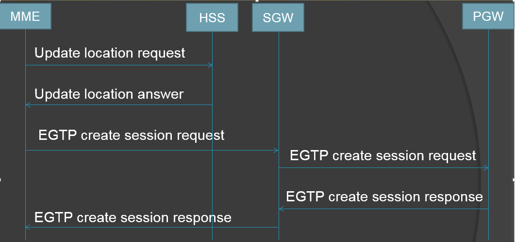
ØNow MEE would send a message that
is UPDATE
LOCATION REQUEST to HSS. So
MME updates to HSS that user is right
now with me and asking for user subscription
related information, APN Configuration
etc.
ØSo, HSS responded with UPDATE LOCATION ANSWER.

ØNow, MME decides and talk with SGW
to create default bearer setup in EGTP
Create
Session Request. And SGW will send same to PGW .
ØOnce this goes to PGW go and check
with PCRF for Qos . PCRF give to PGW Qos and
billing rule.
ØNow PGW send to SGW default bearer
response in EGTP Create Session Response.
And
SGW forwards
the same to MME.
ØNow, MME will send a message to
E-NB that is INITIAL CONTEXT SETUP REQUEST.
ØSo, E-NB triggered to UE as RRC connection Reconfiguration
for new radio bearer
establishment along with these 2 NAS messages.
ØSo, UE responded with rrc
connection reconfiguration complete message and assuring
that he
configured properties of radio bearer on all the layers. Here, E-NB understand that
radio part is created.
ØNow, E-NB replied with INITIAL CONTEXT SETUP RESPONSE to MME.
ØAfter that UE will send 2 NAS
messages that is EMM:
Attach complete and ESM: PDN
connectivity accept along with IP address assigned by PGW. So E-NB
will forward
the
same information
to MME
in UPLINK NAS TRANSPORT message.
ØNow MME will send to SGW that EGTP _ MODIFY BEARER REQUEST and SGW
responded with EGTP _ MODIFY BEARER RESPONSE.
Now, the default bearer is created
. There is radio bearer b/w UE and E-NB, tunnel
created in b/w E-NB to SGW and SGW to PGW. Now all the 3 bearers are
existing.
So default EPS bearer created for
default PDN connectivity.

ECM
( EPS Connection Management)-

When UE has established the both
RRC Connection
and S1 Connection, we say that ECM
connected that is between UE and MME.
It has two states-
1) ECM- Idle
2) ECM- Connected
Brief concept about States-

After moved to idle state----

 Reviewed by LTE/IMS reference
on
February 28, 2018
Rating:
Reviewed by LTE/IMS reference
on
February 28, 2018
Rating:

This comment has been removed by the author.
ReplyDelete