
IMS (IP Multimedia Subsystem)
VoLTE

Universal Integrated Circuit (UICC): Each UE must contain one UICC and each UICC may have one or more of the following modules.


 Transport layer :
 Session Layer:

Sip client:

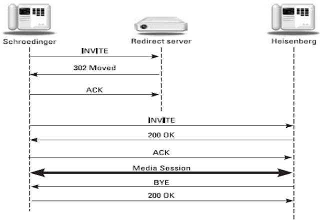
Redirect server- It Provides the client with information about the next hop or hops that a message should take and then the client contacts the next-hop server or UAS directly.
Registrar server-


Branch - ID and Tag ID :
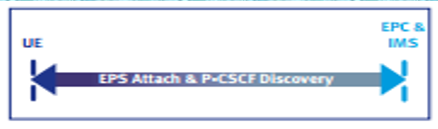 Before sending
any Session Initiation Protocol (SIP) requests, the UE must perform “P-CSCF
Discovery”, the process of identifying (by address) the correct Proxy-Call
Session Control Function (P-CSCF).
Before sending
any Session Initiation Protocol (SIP) requests, the UE must perform “P-CSCF
Discovery”, the process of identifying (by address) the correct Proxy-Call
Session Control Function (P-CSCF).


Call flow between UE and P-CSCF:


VoLTE
Brief description about VoLTE
-
VoLTE,
Voice over LTE is an IMS-based specification. Adopting this approach, it
enables the system to be integrated with the suite of applications that will
become available on LTE.
Voice over
LTE (VoLTE) means better sounding voice calls and the ability to use voice and
data at the same time, among other things.
There are
few
facts
we
should
know about the next-generation wireless network technology.
1. Simultaneous
Voice and Data Calls
2. Better
Quality Voice Calls -
VoLTE enables
what's called high definition (HD) voice calling.
To
make
an HD voice call, we need to use a phone that supports VoLTE.
3. No
Increase in Voice Charges
How IMS is structured-
Below describes the overall IMS
architecture and key protocols.
The IMS core is access independent
which means that same services can be delivered over different types of access
technologies. In the IMS specification the “core” of IMS comprises two main
nodes: the Call Session Control Function (CSCF) and
the Home Subscriber Server (HSS).
In the IMS architecture overview Media Gateway Control Function (MGCF) and
Media Gateway (MGW) have been depicted beside the IMS Core. IMS core is
responsible for session management and media control.
IMS enables a packet-based network
to provide multiple services on single Control/Service Layers via different
access network.
IMS core has the following
important nodes-
Several types of SIP servers known
as CSCF are used to process SIP signalling packets in the IMS domain:
1)Proxy CSCF (P-CSCF)
2)Interrogating CSCF (I-CSCF)
3)Serving CSCF(S-CSCF)
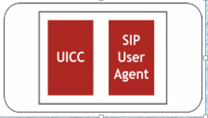
In IMS,
the UE contains a Universal Integrated Circuit Card (UICC) and a Session
Initiation Protocol User Agent (SIP UA).
Universal Integrated Circuit (UICC): Each UE must contain one UICC and each UICC may have one or more of the following modules.
Subscriber Identity Module (SIM):
SIM identity information used by a GSM network.
UMTS Subscriber Identity Module (USIM): USIM
information used by a UMTS or LTE network.
CDMA Subscriber Identity Module (CSIM) or
Re-Useable Identification Module (R-UIM): identity information used
by a CDMA network.
IP Multimedia Services Identity Module
(ISIM): ISIM identity information used by the IMS
subsystem.
()
If
we look
into ISIM which is important when UE wants to use IMS resources in the network.
ISIM contains the following:
IP Multimedia Private Identity (IMPI): IMPI
is a global identity allocated by home network. IMPI contains home operator’s
domain information.
Home
operator’s domain name
(IMSI=MCC+MNC+MSIN)
IP Multimedia Public Identity (IMPU): IMPU
acts like a telephone number which can either be a SIP URI
(sip:<username>@<host>:<port>) or a tel
URI as defined in RFC 39664 (tel:<country_code><national_destination_code><subscriber_number>).
(MSISDN)
Secret Key: This
long secret key is used for user authentication and SIP registration.
SIM, USIM/CSIM and ISIM Overview
Subscriber
Identification Module (SIM)
:
– An
integrated circuit that securely stores the international mobile subscriber
identity (IMSI) and the related key used to identify and authenticate
subscribers on mobile telephony devices
– Initially
introduced in GSM (TS 11.11)
• Key
Information Stored in SIM
– unique
serial number (ICCID) – up to 20 digits
– international
mobile subscriber identity (IMSI)– MCC +
MNC + MSIN
– security
authentication and ciphering information
• Authentication
Key (Ki) - 128-bit unique key for each SIM, also stored in AuC/HSS
– temporary information related to the local network
• Local
Area Identity (LAI) – received from local carrier – a list of the services the
user has access to
• Operator-Specific
Emergency Number
• SMSC
(Short Message Service Centre) number
• Service
Provider Name (SPN)
• Service
Dialling
Numbers
(SDN)
• Advice-Of-Charge
parameters
• Value
Added Service (VAS) applications – two passwords: 1)
a
personal identification number (PIN) for ordinary use and,
2) a personal
unblocking code (PUK) for PIN unlocking.
UMTS SIM (USIM):
Similar to
GSM SIM
– More
capabilities
– allowing
3G UMTS services + 4G LTE
– Stronger
Authentication and Security capabilities
– Larger
and securer phone book
•Key
information
stored
- similar
to GSM SIM
-Additional information
to support UMTS services
CSIM(CDMA SIM)-
Similar to
GSM SIM
– runs
on a UICC
– file
structure derived from the R-UIM card
– For cdmaOne/CDMA2000
• Key
parameters – Identifications • MIN+ESN prior to introduction of IMSI, MIN for
identifying the subscriber and MIN+ESN for registration and authentication •
IMSI (international mobile subscriber identifier). • TMSI (temporary mobile
subscriber identifier, for position security). • UIMID (hardware identifier) -
a pseudo value if EUIMID is in use. • EUIMID Either short form (based on MEID)
or long form (based on ICCID). • ICCID Present even if it is not used as EUIMID
• MEID (hardware identifier). – Encryption keys – Phone Number – List of
services available • Call Control • SMS • BCMCS Broadcast • IP Location –
CDMA2000 Parameters – Stats – Misc.
IP Multimedia Service Identity Module (IMS
SIM) :
– An
application residing on the UICC
– Contains
parameters for identifying and authenticating the user to IMS
– ISIM
can co-exist with (U)SIM and/or CSIM on the same UICC
• ISIM
Application Dedicated File (ADF) Contains multiple Elementary Files (EFs) – IST
(ISIM Service Table): Lists available optional services:
• P-CSCF
address
• Generic
Bootstrapping Architecture (GBA),
• HTTP
Digest
• GBA-based
Local Key Establishment Mechanism,
• Support
of P-CSCF discovery for IMS local break out – DOMAIN (Home Network Domain Name)
• For
3GPP systems without ISMI, UE derives DOMAIN from IMSI – IMPI (IMS Private User
Identity)
• Every
IMS user has one or more IMPIs – assigned by the home network operator
• Used
for Registration, Authorization, Administration and Accounting purposes
• an
ISIM stores ONE IMPI – not modifiable on UE
• Identifies
the subscription, NOT the user
• Is
used to identify the user’s information (e.g. authentication info) stored in
HSS (e.g. for Registration)
• HSS
needs to store the IMPI
• S-CSCF
needs to obtain and store the IMPI upon registration
• For
3GPP systems without ISIM, IMPI can be derived from IMSI
ISIM Application Dedicated File (ADF) Contains
multiple Elementary Files (EFs)
– IMPU
(IMS Public User Identity – one or more)
• Every
IMS user has one or more IMPUs
• IMPUs
are used by users for requesting communications to other users
• IMPU
takes the form of either
– SIP
URI (RFC 3261): sip:username@domain
or
• Both
formats can be used to address users
• At
least one IMPU is stored in ISIM – cannot be modified on UE
• An
IMPU must be registered (explicitly or implicitly) before use for IMS
procedures
• Implicit
registration allows registering a user with multiple IMPUs through one
registration
• IMPUs
are not authenticated during registration
• IMPUs
MAY be used to identify the user’s information in HSS (for mobile terminated
sessions)
• Alias
IMPUs can be grouped and used to identify the same user - stored in HSS
• IMPUs
MAY be shared across multiple IMPIs within the same IMS subscription
• For
3GPP systems without ISIM, Temporary IMPU is derived from the IMSI – AD
(Administrative Data): UE operation mode – normal or type approval) – ARR
(Access Rule Reference): access rules for files located under the ISIM ADF –
P-CSCF: P-CSCF Address (one or more) – GBABP (GBA Bootstrapping parameters):
• RAND
(AKA Random Challenge
• Bootstrapping
Transaction Identifier (B-TID) associated to a GBA NAF derivation procedure –
NAFKCA (NAF Key Centre Address – one or more)
AKA Authentication
• IMS Authentication
– HSS: • Generates and passes
(RAND, AUTN, XRES, CK, IK) to S-CSCF via MAA
– S-CSCF:
• Relays (RAND, AUTN, CK, IK) to P-CSCF via 401(REGISTER), keeps XRES
– P-CSCF:
• Relays (RAND, AUTN) to Mobile Station via 401(REGISTER)
– Mobile
Station: • Calculates RES and send with REGISTER to IMS core
– S-CSCF:
• Compare RES and XRES to complete the authentication
• Notes:
– Random
number (RAND)
– Authentication
token (AUTN)
– Signed/expected
result (XRES)
– Cipher
key (CK)
– Integrity
Key (IK)
– Result
(RES)
IMS
Architecture overview-

CSCF(Call Session Control function ):-
The Call
Session Control function (CSCF) is the heart of the IMS architecture and is
used to process SIP signalling. The main function of the CSCF is to provide
session control for terminals and applications using the IMS network.
Session control includes the secure routing of the SIP messages, subsequent
monitoring of the SIP sessions and communicating with the policy architecture
to support media authorization. It has also the responsibility for interacting
with the HSS.
As shown in above figure CSCF can play three different roles which may
or may not be separate physical entities.
1) Proxy CSCF (P-CSCF)
2) Interrogating
CSCF (I-CSCF)
3) Serving CSCF
(S-CSCF)
P-CSCF
:
(Acts as the first contact point for UEs in the IMS that provides the proxy function by accepting and forwarding service requests, but does not change the Request URI field in the INVITE message.)
(Acts as the first contact point for UEs in the IMS that provides the proxy function by accepting and forwarding service requests, but does not change the Request URI field in the INVITE message.)
Proxy Call
Session Control Function is an IMS (IP Multimedia
Subsystem) element that identified as the mobiles first contact point within
the IM CN (IP Multimedia
Core Network) subsystem. Functions of the P-CSCF include
the forwarding of SIP messages
received from the UE. These may be sent to the I-CSCFor S-CSCF,
depending on the type of message and procedure being carried out. P-CSCF can be located either in a home network or in a visited network.
A P-CSCF is allocated to the IMS
terminal during IMS registration, and does not change for the duration of the
registration. From a standards perspective, the P-CSCF behaves like a SIP
Proxy. In other words, it accepts requests and services them internally or
forwards them onwards.
The P-CSCF
also behaves as a User Agent in some cases. In certain conditions, it
terminates and/or independently generates SIP transactions. Examples of these
cases are when the P-CSCF requests the register for
a user’s registration state updates, when performing P-CSCF initiated
dialog-release etc. At a high level, the P-CSCF performs the following
functions:
• Performs a state
full SIP
proxy function.
• Perform basic validation.
• Perform basic validation.
• Forwards
the SIP REGISTER request received from the UE to an entry point determined
using the
home domain name, as provided by the UE
• Forwards
SIP messages (other than REGISTER) received from the UE to the S-CSCF whose
name
the P-CSCF has received as a result of the registration procedure
• Maintains
mapping between the SIP URI for the subscriber and physical UE IP address as
well as a
Security Association between itself and each UE, for both
authentication and confidentiality
• Forwards
SIP requests or responses from the IMS core to the UE
• Authorizes
bearer resources and QoS management
using the DIAMETER Rx interface to query an
PCRF element
• Ensures
SIP messages received from the UE to the S-CSCF contain the correct, or up to
date,
information about the access network type currently used by the UE (when
the information is
available from the access network)
• Performs
SIP message compression/decompression. Performs
SIP message compression to
reduce the amount of data sent over the radio interface.
• Detects
and manages an emergency session establishment request from the UE
• Generates
CDRs
• P-CSCF
also
plays a role in the detection of IMS Emergency services
I-CSCF
:
(Assigns S-CSCFs to UEs, supports route query, and forwards SIP requests to another IMS domain)
(Assigns S-CSCFs to UEs, supports route query, and forwards SIP requests to another IMS domain)
The Interrogating Call Session
Control Function (I-CSCF) is the home networks first point of contact for peer
IMS networks. It queries the HSS using Diameter Cx
and Dx
interfaces to help in finding the S-CSCF where the user is registered or
selecting a new S-CSCF if the user. It is always located in the home network.
It performs the following
functions-
• Serves
as
the initial point of contact from other networks.
• Performs
a stateless SIP proxy function.
• Selects
a S-CSCF for a user during SIP registration.
• Routes
SIP requests received from another network to the S-CSCF.
• Queries
the HSS for the address of the S-CSCF.
• If no
S-CSCF is currently assigned (e.g., unregistered subscriber), then assigns an
S-CSCF to handle the SIP request.
• Provide
Topology Hiding Interworking Gateway (THIG) function.
(Hiding
is
for security purpose
for example in the time of registration I-CSCF query to HSS to get the authentication vector and profile information and so on. Those are the security things, If we know all the database section someone can easily hack that server for that purpose THIG comes in to the picture).
for example in the time of registration I-CSCF query to HSS to get the authentication vector and profile information and so on. Those are the security things, If we know all the database section someone can easily hack that server for that purpose THIG comes in to the picture).
S-CSCF:
(Acts as the control center of the IMS, implements UE registration and authentication and session control, and provides basic session routing for calling and called parties on the IMS)
(Acts as the control center of the IMS, implements UE registration and authentication and session control, and provides basic session routing for calling and called parties on the IMS)
The Serving Call Session Control
Function (S-CSCF) is the central node for the provision of the SIP signalling
and
the heart of the IMS system or we
can say S-CSCF
is a central function of the signalling plane
in the IMS core network.
It is a SIP server always located in the home network.
The S-CSCF uses
DIAMETER Cx
and Dx
interfaces to the HSS to download and upload user
profiles -
it has no local storage of the user. All necessary
information is loaded from the HSS.
•It handles SIP registrations, which
allows it to bind the user location (e.g. the IP address of the
terminal) and
the SIP address.
•It sits on the path of all signalling
messages,
and can inspect every message.
•It decides to which application server(s)
the SIP message will be forwarded, in order to provide their
services.
•It provides routing services, typically
using ENUM lookups
•It enforces the policy of the network
operator
A number of S-CSCFs may be deployed
for the sake of scalability and redundancy.
E-CSCF (Emergency-CSCF) :
Compared
to other CSCFs, the E-CSCF is a newly defined entity in the IMS network. As its
name indicates, the E-CSCF is responsible for handling of emergency call
service. Once the P-CSCF detects that the received SIP message request is for
an emergency call it forwards that SIP message to the E-CSCF. Then, the E-CSCF
contacts the Locating Retrieval Function (LRF) to get the location of the UE
for routing the emergency call appropriately. The
E-CSCF can be located either in a home network or in a visited network.
North
forge Innovations
is a trusted provider of intellectual capital to world-leading IMS CSCF
providers. Working closely with these customers, North
forge engineers
have analysed,
designed,
implemented and verified key features on IMS CSCF products, and provided
technical support. North forge has
the technical knowledge and innovative implementation skills to support the
development of IMS
CSCF products.
HSS – Home subscriber server:
The Home Subscriber Server (HSS) is the master database that contains user and subscriber information to support the network entities handling calls and sessions.
The Home Subscriber Server (HSS) is the master database that contains user and subscriber information to support the network entities handling calls and sessions.
It provides
the following functions: identification handling, access authorization,
authentication, mobility management (keeping track of which session control
entity is serving the user), session establishment support, service
provisioning support, and service authorization support. When a user registers
in the IMS domain, the user profile (relevant information related to the
services to be provided to the user) is downloaded from the HSS to the CSCF.
For session establishment, HSS provides information on which CSCF currently
serves the user.
When more
than one HSS is deployed in the network, a Subscriber Location Function (SLF) is
needed to locate the HSS that holds the subscription data for a given user.
The Subscription Locator Function
(SLF) is used in a IMS network as a resolution mechanism that enables the
I-CSCF, the S-CSCF and the AS to find the address of the HSS that holds the
subscriber data for a given user identity when multiple and separately
addressable HSSs have been deployed by the network operator.
The SLF expose Dx
and Dh interfaces, which have the same syntax and semantic of the Cx
and Sh
interfaces provided by the HSS.
The SLF does not perform any logic
on its interfaces,
but replies
to the requestor with a REDIRECT message, specifying the address of the HSS
which is able to fulfill the
request received.
Both the HSS and the SLF
communicate through the DIAMETER protocol.


Application servers :
SIP Application
servers (AS)
host and execute services, and interface with the S-CSCF using SIP. An
example of an application server that is being developed in 3GPP is
the Voice call continuity Function
(VCC
Server). Depending on the actual service, the AS can operate in SIP proxy mode,
SIP UA (user agent) mode or SIP B2BUA mode.
An AS can be located in the home network or in an external third-party network.
If located in the home network, it can query the HSS with the Diameter Sh
or Si interfaces (for a SIP-AS).
Media Resource Function (MRF):
The Media Resource Function (MRF) provides media services in the home
network and
implements functionality to manage and process media streams such as voice,
video, text-to-speech, and real-time transcoding of multimedia data.
An MRF
is normally only involved when an IMS application requires to provide a media
service from the network such as playing announcements or mixing media streams
in a multiparty conference and is normally only involved for the duration of
the media service.
Each MRF
in the network can be further divided into a Media
Resource Function Controller (MRFC) – a signalling
plane
node that acts as a SIP User Agent to the S-CSCF - and a Media Resource Function Processor (MRFP) –
a media plane node that provides the essentially transcoding and content
adaptation functionalities.
H.248 protocol is
used between the MRFC and MRFP in order to set up a suitable IP support and to
support the mixed streams.
The Mp
reference point allows an MRFC to control media stream resources provided by an
MRFP. An Application Server can interact with the MRFC either directly (Cr and
Mr’ interfaces) or via the S-CSCF (ISC and Mr interfaces). Having
specialized element like the MRF allows optimizing infrastructure costs by
providing common basic functions across service platforms.
Break Out Gateway Control Function (BGCF) :
A Breakout Gateway Control
Function (BGCF) is a SIP proxy which processes requests for routing from
an S-CSCF when the S-CSCF has determined that the session cannot be routed
using DNS or ENUM/DNS. It includes routing functionality based on telephone
numbers.
The BGCF element plays an important
role in IMS networks as a SIP proxy to route calls between IMS and non-IMS endpoints.
The BGCF
Routing Server can be deployed in several different scenarios to provide this
functionality:
• As the call routing device
between IMS and non-IMS networks, where a call originates on an IMS-based
endpoint and terminates on a PSTN-based endpoint, via a Media Gateway Controller
• As the call routing device
between IMS and circuit-based networks within the same logical network, where a
call originates on an IMS based endpoint
and terminates on a circuit-based endpoint within the same service provider
network, via a Media Gateway
• As the
call routing device between two IMS networks, where a call originates on an
IMS-based network and terminates on a circuit based endpoint
in a service provider network that contains both IMS and non-IMS networks, via
an S-CSCF, IBCF or peering BGCF
Note: If the
breakout occurs in the same network as the BGCF then the BGCF selects a MGCF
(Media Gateway Control Function) that will be responsible for inter-working
with the PSTN
or CS network, and forwards the signalling
to
MGCF. The MGCF then receives the SIP signalling from the BGCF and manages the
interworking with the PSTN network or CS network.
Otherwise it
forwards signalling
to
BCGF of another operator network.
All
the implementations depends upon vendor configuration
whether BGCF selects a MGCF for same network or for another operator network
MGCF(Media Gateway Control Function):
(Enables interworking between the IMS control plane and the legacy CS network)
(Enables interworking between the IMS control plane and the legacy CS network)
A media gateway controller
function (MGCF) is a SIP endpoint that does call control protocol
conversion between SIP and ISUP/BICC and interfaces with the SGW over SCTP. It
also controls the resources in a Media Gateway
(MGW)
across an H.248 interface.
In the case when MGCF works as a
breakout to CS network it is also responsible for managing the conversion of signalling
messages,
converting SIP messaging to the Bearer Independent Call Control (BICC) and ISDN
User Part (ISUP) protocols used in legacy systems.
It performs the following functions
as follows-
- Performs call
control protocol conversion between SIP and ISUP
- interfaces the
SGW over SCTP
- controls the
MGW resources with a H.248 interface
Media Gateway (MGW)
:
The Media Gateway (MGW), controlled
by the MGCF using H.248, is responsible for providing the interworking of media
flows between different networks. It provides interworking between the
different media transport formats, RTP/UDP/IP and TDM, as well as media
transcoding of voice and video, if required.
IBCF:
Interconnect Border
Control Function (IBCF) offers boundary control between
various service provider networks, providing IMS network security in terms of signalling
information. This is
done by implementing a Topology-Hiding Inter-network Gateway (THIG)
sub-function, which performs signalling-based topology
hiding, session screening and IPv4-IPv6 translations based on source and
destination signalling addresses.
When connecting non-SIP or non-IPv6 networks, the IBCF also invokes the
Inter-Working Function and performs bandwidth allocation and admission control
using local policies or through the interface to PCRF elements. The IBCF may
also interact with TrGW for control of the boundary at the
transport layer including NAPT, pinhole firewall, and other features.
SBC (Session Border Control) :
Session Border Controllers (SBC),
which are referred to as boarder control functions in the IMS specifications,
are IP to IP gateways deployed at the border between an operator’s IMS network
and other networks (Network to network interface, NNI). For a broadband access,
the P-CSCF and the policy enforcement functionality can be implemented as a SBC
supporting the User to Network interface, UNI. It manages IMS sessions
(correlating signalling and
media) to ensure Security, QoS,
SLAs, NAT/FW traversal and other critical functions for real time IP streams
where applicable. The session boarder gateway functionality can also be used to
provide address translation; either between private and public IPv4 addresses,
or between IPv4 and IPv6 address.
SBCs commonly maintain full session
state and offer the following functions:
Security –
protect the network and other devices from:
Toll fraud via
rogue media streams
Topology hiding
Malformed packet protection
Connectivity – allow different
parts of the network to communicate through the use of a variety of techniques
such as:
NAT traversal
SIP normalization via SIP message
and header manipulation
IPv4 to IPv6 interworking
VPN connectivity
Quality of service –
the QoS
policy of a network and prioritization of flows is usually implemented by the
SBC. It can include such functions as:
Regulatory – many times the SBC is
expected to provide support for regulatory requirements such as:
emergency calls prioritization
and
Media services – many of the new
generation of SBCs also provide built-in digital signal processors (DSPs) to
enable them to offer border-based media control and services such as:
DTMF relay and interworking
Media transcoding
Tones and announcements
Data and fax interworking
Support for voice and video calls
Statistics and billing information
– since all sessions that pass through the edge of the network pass through the
SBC, it is a natural point to gather statistics and usage-based information on
these sessions.
With the advent of WebRTC some
SBCs have also assumed the role of SIP to WebRTC Gateway and
translate SIP. While no one signalling protocol is mandated by the Web
RTC
specifications, SIP over Websockets (RFC 7118)
is often used partially due to the applicability of SIP to most of the
envisaged communication scenarios as well as the availability of open source
software such as JsSIP.
In such a case the SBC acts as a gateway between the Web
RTC applications
and SIP end points.
SBCs are inserted into the signalling
and/or
media paths between calling and called parties in a VoIP call, predominantly
those using the Session
Initiation Protocol (SIP), H.323,
and MGCP call-signalling
protocols.
In many cases, in order to hide the
network topology and protect the service provider or enterprise packet network,
the session border controller (SBC) will terminate a received call and initiate
a second call leg to the destination party. In technical terms, when used
within the SIP protocol, this is defined as being a back-to-back user
agent(B2BUA).
The effect of this behaviour is
that not only the signalling traffic,
but also the media traffic (voice, video) can be controlled by the SBC. In
cases where the SBC does not have the capability to provide media services on
board, SBCs are also able to redirect media traffic to a different element
elsewhere in the network, for recording, generation of music-on-hold, or other
media-related purposes. Conversely, without an SBC, the media traffic travels
directly between the VoIP phones, without the in-network call signalling
elements
having control over their path.
In other cases, the SBC simply
modifies the stream of call control (signalling) data
involved in each call, perhaps limiting the kinds of calls that can be
conducted, changing the codec choices,
and so on. Ultimately, SBCs allow the network operators to manage the calls
that are made on their networks, fix or change protocols and protocol syntax to
achieve interoperability, and also overcome some of the problems that firewalls
and network address
translators(NATs) present for VoIP calls.
In order
to show how an SBC works one can compare a simple call establishment sequence
with a call establishment sequence with an SBC.In
the simplest session establishment sequence with only one proxy between the
user agents the proxy’s task is to identify the callee’s
location and forward the request to it. The proxy also adds a Via header with
its own address to indicate the path that the response should traverse. The
proxy does not change any dialog identification information present in the
message such as the tag in the From header, the Call-Id or the Cseq.
Proxies also do not alter any information in the SIP message bodies. Note that
during the session initiation phase the user agents exchange SIP messages with
the SDP bodies that include addresses at which the agents expect the media
traffic. After successfully finishing the session initiation phase the user
agents can exchange the media traffic directly between each other without the
involvement of the proxy.
SBCs come in all kinds of shapes
and forms and are used by operators and enterprises to achieve different goals.
Actually even the same SBC implementation might act differently depending on
its configuration and the use case. Hence, it is not easily possible to
describe an exact SBC behaviour that
would apply to all SBC implementations. In general it is possible to identify
certain features that are common to SBCs. For example, most SBCs are
implemented as back-to-back user
agent (B2BUA).
A B2BUA is a proxy-like server that splits a SIP transaction in two pieces: on
the side facing User Agent Client (UAC), it acts as server; on the side facing
User Agent Server (UAS) it acts as a client. While a proxy usually keeps only
state information related to active transactions, B2BUAs keep state information
about active dialogs, e.g., calls. That is, once a proxy receives a SIP request
it will save some state information. Once the transaction is over, e.g., after
receiving a response, the state information will soon after be deleted. A B2BUA
will maintain state information for active calls and only delete this
information once the call is terminated.
When an SBC is included in the call
path, the SBC acts as a B2BUA that behaves as a user agent server towards the
caller and as user agent client towards the callee.
In this sense, the SBC actually terminates that call that was generated by the
caller and starts a new call towards the callee.
The INVITE message sent by the SBC contains no longer a clear reference to the
caller. The INVITE sent by the SBC to the proxy includes Via and Contact
headers that point to the SBC itself and not the caller. SBCs often also
manipulate the dialog identification information listed in the Call-Id and From
tag. Further, in case the SBC is configured to also control the media traffic
then the SBC also changes the media addressing information included in the c
and m lines of the SDP body. Thereby, not only will all SIP messages traverse
the SBC but also all audio and video packets. As the INVITE sent by the SBC
establishes a new dialog, the SBC also manipulates the message sequence number
(CSeq) as well the Max-Forwards value. Note that the list of header
manipulations listed here is only a subset of the possible changes that an SBC
might introduce to a SIP message. Furthermore, some SBCs might not do all of
the listed manipulations. If the SBC is not expected to control the media
traffic then there might be no need to change anything in the SDP header. Some
SBCs do not change the dialog identification information and others might even
not change the addressing information.
SBCs are often used by corporations
along with firewalls and intrusion
prevention systems (IPS) to enable VoIP calls to and
from a protected enterprise network. VoIP service providers use SBCs to allow
the use of VoIP protocols from private networks with Internet connections
using NAT, and also to implement strong security measures that are necessary to
maintain a high quality of service. SBCs also replace the function of application-level
gateways. In
larger enterprises, SBCs can also be used in conjunction with SIP trunks to
provide call control and make routing/policy decisions on how calls are routed
through the LAN/WAN. There are often tremendous cost savings associated with
routing traffic through the internal IP networks of an enterprise, rather than
routing calls through a traditional circuit-switched phone network.
Additionally, some SBCs can allow
VoIP calls to be set up between two phones using different VoIP signaling
protocols (e.g., SIP, H.323, Megaco/MGCP)
as well as performing transcoding of the media stream when different codecs are
in use. Most SBCs also provide firewall features for VoIP traffic (denial of service protection,
call filtering, bandwidth management). Protocol normalization and header
manipulation is also commonly provided by SBCs, enabling communication between
different vendors and networks.
From an IP Multimedia
Subsystem (IMS) or 3GPP (3rd
Generation Partnership Project) architecture perspective, the SBC
is the integration of the P-CSCF and
IMS-ALG at
the signalling
plane
and the IMS Access Gateway at the media plane on the access side. On the
interconnect side, the SBC maps to the IBCF, IWF at
the signalling
plane
and TrGW(Transition
Gateway) at the media plane.
From an IMS/TISPAN architecture
perspective, the SBC is the integration of the P-CSCF and C-BGF functions
on the access side, and the IBCF, IWF, THIG,
and I-BGF functions
on the peering side. Some SBCs can be "decomposed", meaning the signaling
functions can be located on a separate hardware platform than the media relay
functions – in other words the P-CSCF can be separated from the C-BGF, or the
IBCF/IWF can be separated from the I-BGF functions physically. Standards-based
protocol, such as the H.248 Ia
profile, can be used by the signaling
platform to control the media one while a few SBCs use proprietary protocols.
SIP Application Server – (AS) :
A SIP application server - AS is composed of a computer and associated software that is connected to a communication network and provides information services (applications) for clients (users). Application servers are usually optimized to provide specific applications such as database information access or sales contact management. Application servers are a key component of nextgen networks, and an enabler of IP-based enhanced services. These enhanced services will generate much-needed new revenue streams for service providers.
A SIP application server - AS is composed of a computer and associated software that is connected to a communication network and provides information services (applications) for clients (users). Application servers are usually optimized to provide specific applications such as database information access or sales contact management. Application servers are a key component of nextgen networks, and an enabler of IP-based enhanced services. These enhanced services will generate much-needed new revenue streams for service providers.
Examples include
all forms of conferencing, voice mail and unified messaging. Being soft
switch-based, application servers have the
flexibility to easily offer services that go beyond the feature set of legacy
switched telephony. In terms of network configuration, the application server
works in tandem with the media server,
providing it with business logic and instructions for delivering enhanced
services.
Application
Servers host and execute services, and
interface with the S-CSCF using SIP.
This allows
third party providers an easy integration and deployment of their value added
services to the IMS infrastructure. Examples of services are:
– Caller
ID related services (CLIP, CLIR, ...)
– Call
waiting, Call hold, Call pick up
– Call
forwarding, Call transfer
– Call
blocking services, Malicious Caller Identification
– Lawful
interception
– Announcements,
Digit collection
– Conference
call services
– Location
based services
– SMS,
MMS
– Presence
information, Instant messaging
– Voice
Call Continuity Function (VCC Server) or Fixed Mobile Convergence
IMS
Protocol
Stack :
The Open
Systems Interconnect (OSI) model has seven layers. But we have consider only
five layer in IMS protocol stack.
Physical Layer-
It convert the digital data/bit
stream into electrical, light or radio signal over a medium(copper, Fiber
, wireless) through the network at
electrical or mechanical level.
Data Link Layer-
The Data Link layer provides the
reliable transfer of data over a media and
handles error detection not correction, network
topology, flow
control and physical addressing. It combine the packets into bytes and bytes
into frames. It provide the access to the media using the MAC address. It
transmit frame node to node based on station address.
Network Layer(IP): [IP,ICMP,IPX]
The network layer is
responsible for the delivery of individual packets from the source host to the
destination host i.e End to End delivery or source to
destination delivery.
The network layer defines three
main features-
1.Logical addressing –
It define how each device can have an address that can be used by the routing
process.
2.Routing (forwarding)- Routing concepts define how devices
(typically routers) forward packets to their final destination.
3.Path determination- It determination refers to the work
done by routing protocols by which all possible routers are learned, but the
best route is chosen for use.

It provides end to end transport
services –establishes logical connections between hosts. Connection oriented or
connectionless data transfer.

Session establishment, management
and termination for the application between two users.
Key protocols used in the IMS network-
1)Session
Initiation Protocol (SIP)
2)Diameter
– the Authentication, Authorization, and Accounting protocol
3)H.248
media control protocols
4)IPv6
SIP
SIP is the main signalling protocol
used in IMS networks. It was developed by the IETF and was selected by 3GPP as
a standard for IMS.
The function of SIP is to
establish, modify and terminate multimedia sessions – with medias such as
voice, video and chat – over IP networks, where the media delivery part is
handled separately. In SIP there is just one single protocol, which works end-to-end
and supports the establishment and termination of user location, user
availability, user capability, session set-up and session management. SIP is
also designed to enable additional multimedia sessions and participants to be
dynamically added or removed from a session. These are the major reasons SIP
has been selected in IMS; it is also considered to be flexible and secure.
SIP Components:
SIP is a peer-to-peer protocol. The
peers in a session are called user agents (UAs).The
SIP
UA is the logical terminal of the SIP network and both transmits and receives
SIP messaging.
A UA
can function in one of the following roles:
User-agent
client (UAC)--A client application that initiates the SIP request.
User-agent
server (UAS)--A server application that contacts the user when a SIP request is
received and that returns a response on behalf of the user.
Typically, a SIP endpoint is
capable of functioning as both a UAC and a UAS, but functions only as one or
the other per transaction. Whether the endpoint functions as a UAC or a UAS
depends on the user agent that initiated the request.
From an
architectural standpoint, the physical components of a SIP network can be
grouped into two categories: clients (endpoints) and servers.
The figure below illustrates the
architecture of a SIP network.

Sip client:
User-agent client (UAC)--A client
application that initiates the SIP request.
User-agent server (UAS)--A server
application that contacts the user when a SIP request is received and that
returns a response on behalf of the user.
Sip servers:
Proxy
server—Receives
SIP
requests from a client and forwards them on the client’s behalf. Basically,
proxy servers receive SIP messages and forward them to the next SIP server in
the network.
Just as
a router
forwards IP packets at the IP layer, a SIP proxy forwards SIP messages at
the application
layer.
Proxy
servers can provide functions such as authentication, authorization, network
access control, routing, reliable request retransmission, and security.
A proxy server can be either
stateless or state full.
Stateless
proxy:
A stateless proxy server
processes each
SIP request or response based solely on the message contents.
Once the
message has been parsed, processed, and forwarded or responded to,
no information
(such as dialog information) about the message is stored. A stateless
proxy never
retransmits a message, and does not use any SIP timers. Note
that the
stateless loop detection using Via header fields described
in RFC 2543
has been
deprecated (removed) in RFC 3261 in favour of
the use of a mandatory Max-Forwards header
field
in
all requests.
State
full proxy:
A state
full proxy
server keeps track of requests and responses received in
the past,
and uses that information in processing future requests and responses.
For example, a state
full proxy
server starts a timer when a request is forwarded. If no
response to the request is received within the timer period, the proxy will
retransmit the
request, relieving the user agent of this task. Also, a state
full proxy can require user agent authentication.
The most
common type of SIP proxy is a transaction state full proxy.
A
transaction state full proxy keeps state about a transaction but
only for the duration of the
pending request. For example, a transaction state full proxy
will keep
state when
it receives an INVITE request until it receives a 200 OK or a final
failure response (e.g., 404 Not Found). After that, it
would destroy the state information.
State full proxy can be either
transaction state full or call state full.
Transaction
state full –
This proxy keep the state of the transaction details.
Call state full-
This
proxy keep the transaction state as well as session state. Ex. S-CSCF

Redirect server- It Provides the client with information about the next hop or hops that a message should take and then the client contacts the next-hop server or UAS directly.
A redirect server was introduced as
a
type of SIP server that responds to, but
does not forward, requests, he
will read the address and he will try to find out where the message need to be forwarded,
his
not
duty to forwarding the packets. Like
a proxy server, a redirect server uses a
database or location service to lookup a user.

Registrar server-
The registrar
server accepts registration requests from user agents. It helps users to
authenticate themselves within the network. It stores the URI and the location
of users in a database to help other SIP servers within the same domain.
Take a look at the following
example that shows the process of a SIP Registration.
Here the caller wants to register
with the TMC domain. So it sends a REGISTER request to the TMC’s Registrar
server and the server returns a 200 OK response as it authorized the client.

B2BUA(Back to Back User Agent):
A back-to-back user agent (B2BUA)
is a logical network element in SIP applications. It is a type of SIP UA that
receives a SIP request, then reformulates the request, and sends it out as a
new request.
Unlike a proxy server, it maintains
dialog state and must participate in all requests sent on the dialogs it has
established. A B2BUA breaks the end-to-end nature of SIP.
B2BUA
– How it Works?
A B2BUA agent operates between two
endpoints of a phone call and divides the communication channel into two call legs.
B2BUA is a concatenation of UAC and UAS. It participates in all SIP signalling
between both ends of the call, it has established. As B2BUA available in a
dialog service provider may implement some value-added features.
In the originating call leg, the
B2BUA acts as a user agent server (UAS)
and processes the request as a user
agent client (UAC) to the destination end,
handling the signalling between end points back-to-back.
A B2BUA maintains the complete
state for the calls it handles. Each side of a B2BUA operates as a standard SIP
network element as specified in RFC 3261.
A
B2BUA provides the following functions −
-Call management
(billing, automatic call disconnection, call transfer, etc.)
-Network interworking
(perhaps with protocol adaptation)
-Hiding of
network internals (private addresses, network topology, etc.)
Often,
B2BUAs are also implemented in media gateways to bridge the media streams for
full control over the session.
Another common type of B2BUA is
known as a Session Border Controller (SBC).
Example:
P-CSCF, TAS, MGCF,MGW,SBC ….This all are
dependent on vendor implementation.
Transaction/Session/ Dialog:
Transaction:
Request
followed by a final response(2xx,3xx,4xx,5xx,6xx). Identifier- cseq
+branch id.
Session:
End
to end media session between two UA’s. Identifier-
RTP.
Dialog:
Peer
to peer communication between two user agents.
Identifier-
From tag+ To tag + Call id.
SIP -Forking:
Sometime a
proxy server forwards a single SIP call to multiple SIP endpoints. This process
is known as forking. Here a single call can ring many endpoints at the same
time.
With SIP forking, we
can
have our
desk
phone ring at the same time as our softphone
or a SIP phone on our mobile, allowing we
to
take the call from either device easily.
Generally, in an office, suppose
boss unable to pick the call or away, SIP forking allow the secretary to answer
calls his extension.
Forking will be possible if there
is a state
full proxy
available as it needs to perform and response out of the many it receives.
We have two types of forking −
-Parallel
Forking
-Sequential
Forking
Parallel Forking
In this scenario, the proxy server
will fork the INVITE to, say, two devices (UA2, UA3) at a time. Both the
devices will generate 180 Ringing and whoever receives the call will generate a
200 OK. The response (suppose UA2) that reaches the Originator first will
establish a session with UA2. For the other response, a CANCEL will be
triggered.
Sequential Forking :
In this scenario, the proxy server
will fork the INVITE to one device (UA2). If UA2 is unavailable or busy at that
time, then the proxy will fork it to another device (UA3).
Branch - ID and Tag ID :
Branch IDs help proxies to match
responses to forked requests. Without Branch IDs, a proxy server would not be
able to understand the forked response. Branch-id will be available in Via
header.
Tags are used by the UAC to
distinguish multiple final responses from different UAS. A UAS cannot resolve
whether the request has been forked or not. Therefore, it need to add a tag.
Proxies also can add tags if it
generates a final response, they never insert tags into requests or responses
they forward.
It may be possible that a single
request can be forked by multiple proxy servers also. So the proxy which would
fork shall add its own unique IDs to the branches it created.
Call
leg and Call ID
:
A call leg refers to one to one
signalling relationship between two user agents. The call ID is a unique
identifier carried in SIP message that refers to the call. A call is a
collection of call legs.
A UAC starts by sending an INVITE.
Due to forking, it may receive multiple 200 OK from different UAs. Each
corresponds to a different call leg within the same call.
A call is thus a group of call
legs. A call leg refers to end-to-end connection between UAs.
The CSeq spaces in the two
directions of a call leg are independent. Within a single direction, the
sequence number is incremented for each transaction.
================================================================================
SIP is based around
request/response transactions, in a similar manner to the Hypertext Transfer Protocol (HTTP).
Each transaction consists of a SIP request (which will be one of several
request methods), and at least one response.
14
SIP request/Methods:
Basic SIP Requests
REGISTER:
allows
Clients to register their current location (one or more addresses)/
or Initially the client should register
with network first.
INVITE:
is used to initiate a call. To initiate create a session. or/ To establish the media session between
two user agent.
ACK:
is sent by a client to confirm that it has received a final response from a
server, such as 200 OK./ To
acknowledge the final response of the Invite.
BYE:
is sent either by the calling agent or by the caller agent to abort a call/
To terminate the attempted session.
CANCEL:
can be sent to abort a request that was sent previously as long as the server
has not yet sent a final response./ To terminate the pending session.
OPTIONS:
It
is used to check the UA’s capabilities and its availabilities.
SUBSCRIBE:
To get the future notification for a particular event.
[ The Event
header field
is
used in a SUBSCRIBE or NOTIFY methods
to
indicate which event package is being used by the
method. In a SUBSCRIBE, it lists
the event package to which the client would like to subscribe.
In a NOTIFY, it lists the event package that the notification
contains state information about.
Event: It is used to indicate which
event package is being used by the method.
An example
follows:
Event: dialog,
o: refer,
reg]
NOTIFY:
To
get the occurrence of a particular event.
PUBLISH:
It
is used by UA to send or publish event state information to a server.
MESSAGE:
allows to send an instant message
REFER:
It
is used by UA to another UA to access the URI/URL scheme.
PRACK:
To
acknowledge the receipt of reliable transmitted of Provisional responses.
UPDATE:
It is used modify/Change state of session without changing the state of dialog.
INFO:
Exchange of any application layer information (e.g. DTMF)
It is used by sip network
elements to transmit digits out of band as telephone events in a reliable
manner independent of the media stream.
It is specially used to carry the
mid call signaling.
SIP
Responses
A SIP response is a message
generated by a user agent server (UAS) or SIP server to reply a request
generated by a client. It could be a formal acknowledgement to prevent
retransmission of requests by a UAC.
- A response
may contain some additional header fields of info needed by a UAC.
- SIP has
six responses.
- 1xx to
5xx has been borrowed from HTTP and 6xx is introduced in SIP.
- 1xx is
considered as a provisional response
and the rest are final responses.
For examples- “1xx”
for provisional responses with a code of 100–199
1xx
Informational – (Provisional
response) Request received, continuing to process request.
Ex.- 100 trying, 180 Ringing, 181
Call is being forwarded, 181 Queued, 183 session progress, 199 Early Dialog
terminated.
2xx Success – Action was successfully received,
understood and accepted.
Ex.-200 OK, 202 Accepted, 204 No
Notification.
3xx Redirection –
Further action needs to be taken in order
to complete the request.
Ex.- 300 Multiple
Choices,301 Moved permanently, 302 Moved
Temporarily
, 305 Use Proxy, 380 Alternative Service.
4xx
Client Error – Request
contains bad syntax or cannot be fulfilled at this server.
Ex.- 400 Bad Request,401
Unauthorized,402 Payment Required,403 Forbidden,404 Not Found,405 Method not
Allowed,406 Not Acceptable, 407 proxy authentication
required , 408 request timeout , 409 conflict, 410 Gone, 412 conditional
request failed,413 Request entity
too large, 414 request URI too long, 415 Unsupported media type,416 Unsupported
URI scheme,417 unknown resource priority,420 bad extention,421 extension
required,422 session interval too small,423 interval too brief,428 use identity
header,429 provide referrer identity,480 temporarily unavailable,481
Transaction/Dialog doesn't exist,482 loop detected ,483 too many hops,484
address incomplete,485 ambigious,486 busy here,487 request terminated,488 not
acceptable,489 bad event,491 request pending ,493 request undecipherable,494
security agreement required.
5xx Server Error –
Server failed to fulfil an apparently
valid request.
Ex.-500 server internal error,501
Not implemented,502 Bad Gateway,503 Service Unavailable,504 Server Timeout, 505
Version Not Supported, 513 Message too large, 580 precondition failure.
6xx
Global Failure – Request is invalid at any server.
Ex. 600 Busy
Everywhere,
603
Decline,604
does not exist anywhere, 606 not acceptable.
P-CSCF Discovery-

The P-CSCF
address may be discovered in one of three
different ways:
1. It may
be stored in the IP Multimedia Services Identity Module (ISIM).
2. The
UE may request it as part of the PDN connectivity request during the Attach process.
[After successfully attached with the network
UE will send PDN connectivity request for APN:IMS. If we the log in ‘create
session
response’ PGW will assign the IP address of
the P-CSCF.]
3. The
UE may request an IP address and Fully Qualified Domain Name (FQDN) from a DHCP
server and then perform a DNS query on the returned IP address and FQDN.
The next
part of the procedural flow includes IMS Registration, Event Subscription and
Call Connection and utilizes key IMS protocols.
IMS Registration:
In Full IMS registration, it can be
split into three major process as shown below-
1) Unauthenticated IMS
Registration Attempt (Unprotected port-5060 )
2) IPSec Security
Association Establishment
3) Authenticated IMS
Registration
(Protected
port-5067)
1. First REGISTER (Path : UA1 --> eNodeB --> S-GW --> P-GW -->
P-CSCF)
SIP REGISTER message go through all
the LTE radio access network and arrives at P-CSCF first (All the IMS/SIP
message goes through P-CSCF). There can be wide differences in terms of the
detailed parameters, but typical format of SIP REGISTER message would like as
follows.
Example:
REGISTER sip:hims.net SIP/2.0,
Via: SIP/2.0/UDP
UE-IP; branch=0abab,
Route: sip:[P-CSCF-IP], // Route specifies the IP of next node for this REGISTER to reach.
In this case,
//'Next
Node' is P-CSCF
Max-Forwards: 20,
From:
<sip:name@hims.net>;tag=abbb,
To: <sip:name@hims.net>,
Contact: <sip:[UE-IP]>;expires=90000,
Call-ID: ababab,
CSeq: 25 REGISTER,
Security-Client: port-s, port-c,
Authorization: Digest username = name.private@hims.net,
Content-Length: 0
Note :
Since
this step is 'REGISTER' process, 'Authentication' parameter does not carry any
specific information for Authentication algorithm. Following is one example
that I captured from test equipment.
Authorization: Digest uri="sip:test.3gpp.com",
username="001010123456789@test.3gpp.com",
response="",
realm="test.3gpp.com",
nonce=""
2. DNS Query for I-CSCF IP (Path : P-CSCF --> DNS Server)
Once P-CSCF get the SIP REGISTER,
it has to find I-CSCF to pass the message to. To find the I-CSCF, P-CSCF to
perform DNS query process (there can be other mechanism to find I-CSCF).
At first, P-CSCF send DNS Query to
DNS server requesting IP address of I-CSCF.
3. DNS Response for I-CSCF IP (Path :
DNS Server --> P-CSCF)
DNS server send response to P-CSCF
with I-CSCF IP address.
4. REGISTER (Path : P-CSCF --> I-CSCF)
Now P-CSCF forward the SIP REGISTER
to I-CSCF.
REGISTER sip:hims.net SIP/2.0,
Via: SIP/2.0/UDP
pcscf1.vims.net; branch=0aab1,
Via: SIP/2.0/UDP
UE-IP;
branch=0abab,
Max-Forwards: 19,
From: <sip:name@hims.net>;tag=
abbb,
To: <sip:name@hims.net>,
Contact: <sip:[UE-IP]>;expires=90000,
Call-ID: ababab,
CSeq: 25 REGISTER,
Content-Length: 0,
Authorization: Digest username = name.private@hims.net
integrity protection: no
5. User Authorization Request (Path :
I-CSCF --> HSS)
Once I-CSCF
got the SIP REGISTER message, it talks to HSS
to get the detailed subscriber information for the UA.
And with UAR (Diameter User
Authentication Request), HSS retrieves authentication information and S-CSCF
information. (This is very simplified description, in reality this process
would be much more complicated).
6. User Authorization Answer (Path : HSS
--> I-CSCF)
With UAA(Diameter
User Authentication Answer), HSS send Authorized Answer and S-CSCF information
to I-CSCF.
- S-CSCF Name,
- S-CSCF Capabilities (load
balancing)
7. REGISTER (Path : I-CSCF -->
S-CSCF)
Now I-CSCF forward the REGISTER
message to S-CSCF.
REGISTER sip:hims.net SIP/2.0,
Via: SIP/2.0/UDP
icscf1.hims.net;branch=0aab2,
Via: SIP/2.0/UDP
pcscf1.vims.net;branch=0aab1,
Via: SIP/2.0/UDP
UE-IP;branch=0abab,
Route: sip:scscf1.hims.net,Max-Forwards:
18,
From:
<sip:name@hims.net>;tag=abbb,
To: <sip:name@hims.net>,
Contact: <sip:[UE-IP]>;expires=90000,
Call-ID: ababab,
CSeq: 25 REGISTER,
Content-Length: 0,
Authorization: Digest username
=name.private@hims.net integrity protection: no
8. Multimedia Authentication Request
(Path : S-CSCF --> HSS)
S-CSCF send
MAR (Multimedia Authentication Request) to HSS.
9. Multimedia Authentication Response
(Path : HSS --> S-CSCF):
HSS sends MAA (Multimedia
Authentication Answer) to S-CSCF with the following information.
S-CSCF does followings at this point-
-Select
Authentication vectors [Random number (RAND), Authentication
token (AUT), signed
result (XRES), Cipher key (CK),
and Integrity Key (IK)]
-Save
the
selected authentication vector
10. 401 Unauthorized (Path : S-CSCF --> I-CSCF):
The user is currently not
authenticated. so the registration request is rejected.
S-CSCF forward
the Authentication information to I-CSCF. Followings are some of the important
parameters. The terminal is challenged to authenticate the user. RAND, AUTN, CK
and IK are passed in the WWW-Authenticate header.
Via:
icscf1, pcscf1, ue-ip
WWW-Authenticate: nonce=RAND-AUTN, ck, ik.
Note : This
message will tell UE to initiate 'REGISTER' with authentication based on the
information under 'WWW-Authenticate'. An example is as follows.
WWW-Authenticate: Digest
realm="test.3gpp.com",
nonce="qlWqVapVqlWqVapVqlWqVUUQA5HEt9VVZ3t1TM221cg=",
qop="auth",
opaque="MTcyMjU3ODA2NDo=SU1TLVNJUCBTZXJ2ZXI=",
algorithm=AKAv1-MD5
Example
:
1. 401 UnAuthorized (Path : I-CSCF --> P-CSCF)
I-CSCF forward the Authentication
information to P-CSCF. Followings are some of the important paramters.
WWW-Authenticate: nonce=RAND-AUTN, ck,
ik,
Via: pcscf1, ue-ip
P-CSCF does followings at this
point
-Save CK and IK
- allocate P-CSCF
side client and server ports
12. 401 UnAuthorized (Path : P-CSCF --> P-GW
--> S-GW --> eNodeB --> UA1)
P-CSCF forward the Authentication
information to UE through LTE Access network. Followings are some of the
important parameters.
WWW-Authenticate:
nonce=RAND, AUTN,
Security-Server: port-s, port-c
The P-CSCF saves the ciphering and
integrity keys. These keys will be needed for establishing the IPSec security
association.
The P-CSCF allocates the subscriber
side client and server ports. These ports will be included in the 401
Unauthorized message sent to the Subscriber.
Pass the RAND and AUTN values to
the subscriber. The CK and IK are removed from the WWW-Authenticate header. The
P-CSCF side client and server ports are also included in the message. The
message itself is sent on the standard SIP port 5060
Authenticate the IMS network by
verifying the authentication token (AUTN). Also compute the RES value that will
be passed back to the IMS network for user authentication.
After
that, The Subscriber has now established the IPSec
security associations with the P-CSCF.
Establish IPSec
security associations for all the client and server port.
Example:
13. Second REGISTER (Path : UA1 --> eNodeB --> S-GW --> P-GW -->
P-CSCF)
This time the message is protected
by IPSec
and the message is addressed to the P-CSCF server port(5067)
passed
in the 401 Unauthorized message. The message contains the RES in the
Authorization header.
Via: UE-IP;UE-Server-Port,
Route: pcscf1, pcscf-server-port,
Contact: UE-IP ue-server-port,
Authorization: Digest
username="001010123456789@test.3gpp.com",
realm="test.3gpp.com",
uri="sip:test.3gpp.com",
qop=auth,
nonce="qlWqVapVqlWqVapVqlWqVUUQA5HEt9VVZ3t1TM221cg=",
………same RAND no which received form 401 un-authorized message
nc=00000001,
cnonce="11259375",
algorithm=AKAv1-MD5,
response="a3f549b13f477562f4445b7277cd83c1", ………. X-REX value
opaque="MTcyMjU3ODA2NDo=SU1TLVNJUCBTZXJ2ZXI="
Example:
14. REGISTER (Path : P-CSCF -->
I-CSCF)
Now P-CSCF Pass the same REGISTER
message to the I-CSCF. This time the Authorization header indicates that
integrity protection is enabled.
via:
pcscf1 UE-IP;UE-Server-Port,
Contact: UE-IP ue-server-port,
Authorization: Digest username =
name.private@hims.net response=RES integrity protection: yes,RES
15.User Authorization Request (Path :
I-CSCF --> HSS)
Query the HSS to assign the S-CSCF.
16. User Authorization Response (Path :
HSS --> I-CSCF)
HSS replies with the S-CSCFs.
S-CSCF Name,
S-CSCF Capabilities
(load balancing)
Note: Why
I-CSCF every time asking for address of S-CSCF to HSS ? Because I-CSCF is a state
less proxy.
17. REGISTER (Path : I-CSCF -->
S-CSCF)
The second
SIP REGISTER
message is finally delivered to the S-CSCF.
Via: icscf1,
pcscf1
,UE-IP;UE-Server-Port,
Contact: UE-IP ue-server-port,
Authorization: Digest username
=name.private@hims.net response=RES integrity protection: yes,RES
18. Server Assignment Request (Path :
S-CSCF --> HSS)
This request is triggered for
subscriber related
information from
the HSS.
19. Server Assignment Answer (Path: HSSà S-CSCF)
Server Assignment Answer Received
subscriber related information.
Now S-CSCF
Compare
the RES reported by the subscriber with the XRES
value.
20. 200 OK (Path : S-CSCF --> I-CSCF)
The RES and the XRES matched, so
the S-CSCF replies with success.
21. 200 OK (Path :
I-CSCF-àP-CSCF -àUE)
The success is relayed back to the I-CSCF,P-CSCF
and then at last reach to UE.
Third
party REGISTRATION(TPR):
After the successful
registration
of UE with network. S-CSCF is
going for TPR because where S-CSCF only
provide session routing and session establishment. For the
needful of server logic provided by TAS like RCS(SMS,
Jiochat, Jio CinemaJio etc.) ,
VoLTE features
(call hold/un-hold, call conference) TPR
required to let the TAS know UE is registered with network.
Example:
1. S-CSCF
has initiate REGISTER request towards TAS
2. TAS has responded ‘200 OK ‘
for the INVITE .
Note:
1. What
is Dialog and transaction? How many transactions are there in single call? (For SIP and IMS)
For
IMS: 5( INVITE,PRACK, UPDATE- optional, ACK, BYE)
For SIP: 3 (INVITE, ACK, BYE)
2. What
are the private(P) headers
in IMS ?
List of P(private) headers are as
follows:
A. P-Associated-URI
The registrar inserts the
P-Associated-URI header field into the 200
OK response to a REGISTER request.
The header field value is populated with a list containing
zero or more URIs that are associated to the address-of-record.
If the registrar supports the
P-Associated-URI header extension, then the registrar MUST always insert the
P-Associated-URI header field in all the 200 OK responses to a REGISTER
request, regardless of whether the REGISTER was an initial registration, re-registration,
or de-registration and regardless of whether there are zero or more associated
URIs.
B. P-Called-Party-ID (Optional header)
When A party initiate a INVITE for
the call and it will reached to B Party S-CSCF.
So, Before retarget
process in B
Party S-CSCF it will carry the R-URI from UE side in P-Called-Party Header
(Retarget
means reformulate the request URI) and it will send to the B party
for more understanding.
C. P-Visited-Network-ID
Identification string of the
visited network. It is used during registrations, to indicate to the user's
home network which network is providing services to a roaming user, so that the
home network is able to accept the registration according to their roaming
agreements.
D.
P-Access-Network-Info(PANI)
It is used access the information
like the cell id and which network it is connected.
E. P-Charging-Function-Addresses
The P-Charging-Function-Addresses
header field is applicable whenever the following
circumstances are met:
1. A UA sends a REGISTER or dialog-initiating
request (e.g., INVITE request)
or a standalone transaction request outside a dialog to a proxy located in the administrative
domain of a private network.
2. A registrar, proxy, or UA that is located in
the administrative
domain of
the private network wants to generate charging records.
3. A registrar, proxy, or UA that is located in
the private network has access
to the addresses of the charging function entities for that network.
4. There are other proxies that are located in
the same
administrative domain of the private network and that generate
charging
records or charging events. The proxies
want to send,
by means
outside SIP, the charging information to the same
charging collecting
entities than the first proxy.
This P-Charging-Function-Address header
contains the following fields:
CCF
—the charging data function addresses used for
offline billing
ECF
—the charging data function addresses used for
online billing
SIP proxy may have preconfigured these
addresses, or
may obtain them from a subscriber database.
Example:
P-Charging-Function-Addresses:
ccf1=135.18.232.565;
ccf2=135.18.232.766
//ecf
= 136.17.235.788
//ecf
= 136.17.235.789
F. P-Charging-Vector
The
P-Charging-Vector header field is used to convey charging-related information,
such as the globally unique IMS Charging Identity (ICID) value.
A
SIP proxy that receives a SIP request that contains a P-Charging -Vector header
field can use the values, such as the globally unique ICID, to produce charging
records
(CDR).
Normal
SIP Call with P-Charging-Vector header
The
P-Charging-Vector
header containing the parameters icid-value and orig-ioi is interworked from I-CSCF network
to the SIP B leg in the INVITE
The
P-Charging-Vector header containing the parameters icid-value,
orig-ioi, and
term-ioi is interworked back from the B side
to the I-CSCF network in the 183 Session Progress and 200 OK INVITE responses.
H. P-Preferred identity-
If one or more contact address is
bind with UE .It will prefer a single contact address.
The P-Preferred-Identity header
field consists of one or two address specifications (a URI with an optional
display name). If there is one address, it MUST contain a sip, sips or tel
URI. If there are two, then one MUST contain a sip or sips URI and the other a tel
URI.
If a P-Preferred-Identity header
field is present in the message that a proxy receives from an entity that it
does not trust, the proxy MAY use this information as a hint suggesting which
of multiple valid identities for the authenticated user should be asserted.
The P-Preferred-Identity header
field can be used by a UAC to indicate the identity or identities it wishes its
trusted proxy to authenticate for. The proxy will use this information with
the P-Asserted-Identity header
field within its Trust Domain.
G. P- Asserted identity -
It
will check and act as a verified caller id for further request and responses.
The P-Asserted-Identity
header field consists of one or two address specifications (a URI with an
optional display name). If there is one address, it MUST contain a sip, sips or
tel
URI. If there are two, then one MUST contain a sip or sips URI and the other a tel
URI.
When a proxy forwards a message to
another node, it must first determine if it trusts that node or not. If it
trusts the node, the proxy does not remove any P-Asserted-Identity header
fields that it generated itself, or that it received from a trusted source. If
it does not trust the element, then the proxy MUST examine the Privacy header
field (if present) to determine if the user requested that asserted identity
information be kept private.
3. What
is the significance of Path header in IMS?
It will give the P-CSCF address to
the Device for future response.
Request
message: Supported header: Path
Response
message: Path:
sip:term@pcscf.v4.ims.test:4060;lr
Sometimes the
Path header field is a SIP extension
header field with syntax very
similar to the Record-Route header field.
It is used in conjunction with
SIP REGISTER requests and with 200 class messages in
response to
REGISTER (REGISTER responses).
Example:
4. Difference between Record Route, Route and Via header ?
Record
Route: list
out the proxies between two user agents.
Route:
Send
the request to the desired path(e.g=
proxy) followed by Record Route(Strict
Routing).
It is not mandatory that device has
to follow the Record Route. If any nodes goes down in between then routing will
be different. This is called Loose Routing.
Via: Via header
field
is
used to record the SIP route taken by a request and is
used to route a response back to the originator.
Via is used by UAS to
determine
target to send immediate response.
So
when
UAS responds back, it sends all Via without any modification.
Now each
proxy deletes its corresponding via, finally when
response is received at endpoint , endpoint sees its own via only
SUBSCRIPTION : (UE <--------> P-CSCF)
SUBSCRIBE:
SUBSCRIBE initiates for
subscription to the application server for the event REGISTER. The
Presence Server (PS) performs the necessary authorization checks to
ensure
it is allowed the Resource List. If all privacy conditions are met,
PS sends a 200 (OK) response to the I-CSCF. 200 (OK) is passed all the way
to USER.
RLS generates a NOTIFY request including the subscription state as a result of
the SUBSCRIBE request. The NOTIFY gets routed to the subscriber
via
the S-CSCF and P-CSCF. Corresponds to that Device sends
200 OK response for the NOTIFY message.
Call flow between two user agents:
Call flow between UE and P-CSCF:
INVITE:
It is
a SIP method is used to establish the media session between two user agents.
The INVITE request contains a
number of header fields. Header fields are named attributes
that provide additional information about a message.
INVITE
include a unique identifier for the call, the destination address, Calling
Party Address, and information about the type of session that the requester
wishes to establish with the server.
-
This
example
contains a minimum required header fields. The
header fields are briefly described below:
Via -//Contains
the
address at
which
sender
is
expecting to receive responses to this request.
//Via header
field is used to record the SIP route taken by a request and is used to route a
response back to the originator.
//Via is
used by UAS to determine target to send immediate response.
So
when UAS responds back, it sends all Via without any modification. Now each
proxy deletes its corresponding via, finally when
response is received at endpoint , endpoint sees its own via only.
To -
Contains a display name (Receiver/Bob) and
a SIP or SIPS URI towards which the request was
originally directed.
From -
Also contains a display name (Sender/Alice)
and a SIP or SIPS URI that indicate
the originator of the request. This header field also has a tag parameter
containing a random string that was
added to the URI by the sender. It
is used for identification purposes.
Call-ID -
Contains a globally unique identifier for the call,
generated by the combination of a random string and the sender's
host
name or IP address. The combination of the To tag, From tag, and Call-ID
completely defines a peer-to-peer SIP relationship between Alice and Bob and is
referred to as a dialog.
CSeq:
Command
Sequence, contains an integer and a method name. The CSeq number is
incremented for each new request within a dialog and is a traditional sequence
number.
Contact -
Contains a SIP or SIPS URI that represents a direct route to contact Alice,
usually composed of a username at a fully qualified domain name (FQDN). While
an FQDN is preferred, many end systems do not have registered domain names, so
IP addresses are permitted. While
the Via header field tells other elements where to send the response, the
Contact header field tells other elements where to send future requests.
Max-Forwards -
Serves to limit the number of hops a request can make on the way to its
destination. It consists of an integer that is decremented by one
at each hop.
If the
Max-Forwards value reaches 0 before the request reaches its destination, it is
rejected with a 483 (Too Many Hops) error response
Max forward-70
Content-Type -
Contains a description of the message body(SDP) .
Content-Length -
Contains an octet (byte) count of the message body.
INVITE for VT (Video) Call with SDP
parameter:
Re-INVITE
The RE-INVITE message permits the
CSP to change parameters of an existing or pending call.
For example, the RE-INVITE message
is used with Session Timers to allow the CSP to regularly "ping" the
far end to ensure that they are active.
It is not mandatory to change the
codecs (Coder-Decoders) at runtime using the RE-INVITE message.
The following is supported
- RE-INVITE messages that change
the port to which media should be sent.
- RE-INVITE messages that change
the connection address or media type.
- Hold/Release and SUSPEND/RESUME
RTP streams (connection address is zero).
- Initial INVITE messages on hold.
- For upgrading(voice to video) and
downgrading (video to voice) call.
- RE-INVITE messages for FAX (T.38
and Bypass).
We need
to know that re-INVITE is not a new message. A re-INVITE looks just like any
other INVITE. In fact, if we saw a re-INVITE out of the context of its call
flow, we might not be able to tell it from an INVITE used to create a new
session. We will see most of the same headers and a similar message
body. The one exception is that you will see a tag on the To
header. This clues that something is different.
A Re-INVITE, it comes after a session has
been established. This means that it will apply to an existing INVITE after a
final response has been received and an ACK has been sent.
What are the cases INVITE initiates-
1.
Device/DUT has initiated Fresh INVITE
for audio call
Call
Scenario:
1)Normal Audio and Video call between
two users. (on-net/off-net)
2)Audio and video call hold –unhold
3)video call
pause the camera-then hold –then unhold-
then unpause
4)3-4 party Conference call
5)Call forwarding – condition when
a) Always forward
b) When busy
c) When unanswered
d) When unreachable
6)Emergency call 112, 100
7)Customer care number
CALL FLOW from switch off-
Step 1: When Device going to switch/Flight
off mode.
Step2: Device will initiate fresh Attach request after going to
switch /flight ON mode
Step3: After initiating PDN connectivity request for IMS
device will start for IMS registration
4.
Device is initiate subscribe request
for registration in event header through reg event.
5. Device A (b0b1) initiates a voice
call towards B Party (e0a4)) and call got successfully established
6. Now
Device A (b0b1) put the call on hold to B party (a0a4) and same has
successfully established.
More information pending to be updated
 Reviewed by LTE/IMS reference
on
March 15, 2018
Rating:
Reviewed by LTE/IMS reference
on
March 15, 2018
Rating:

No comments: