
RLC(Radio Link Control)

The rule for TM mode is to send all the data in one single TTI(Transmission of time interval-1 ms).

Transmission side-
2) UMD PDU


There can be different types of header. RLC headers will be configured based on the what configuration we will use. This configuration will known by at the time of RRC connection establishment in ‘RRC connection setup’ message.

AM RLC entity contain the sending block and receiving block.


AMD PDU with 16 bit SN (length of LI field is 11 bits) (Odd number of LIs, i.e. K = 1, 3, 5, …)

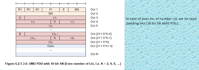
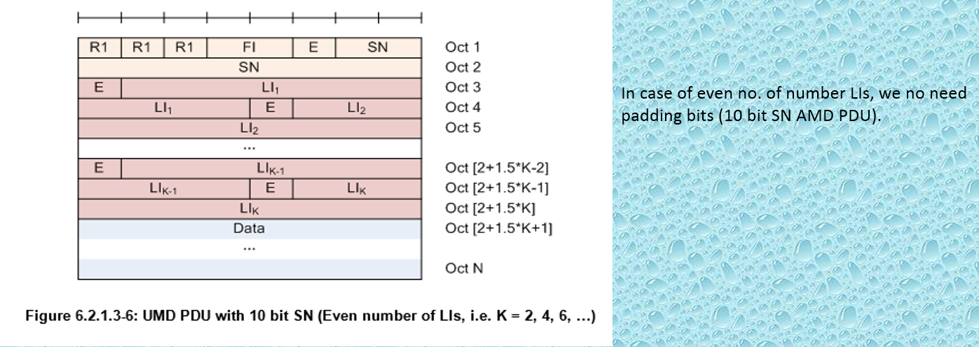
AMD PDU with 10 bit SN (length of LI field is 11 bits) (Even number of LIs, i.e. K = 2, 4, 6, …)

AMD PDU with 16 bit SN (length of LI field is 11 bits) (Even number of LIs, i.e. K = 2, 4, 6, …)

Example- How to make AMD PDU.
In 2nd TTI, MAC is asking for 4815 bytes for the 2nd packet.


In 3rd TTI, MAC is asking for 804 bytes for the 3rd packet.

Now this we have transmitted to the other side and we are expecting acknowledgement (status) whether the packets are successfully received or not.

Case1:

Case2:
Assume that above out of three packets two (1st and 3rd packets) are successfully received and 2nd packets (Full packet) is missing. Then the acknowledgement would be-
When E1 =0 that means no more sequence number is missing. So we have only one sequence number (2nd packet) is missing.
In this case both E1 and E2 are ‘0’ ,indirectly meaning is second packet
is completely missing and no more negative sequence number.
Functions of RLC -
1) Buffering
and waiting for MAC instructions.
2) Reliability
3) Segmentation
and Concatenation based on MAC instructions.
If we want to reliability what
exactly header field that we need?
Sequence
number- Because verification will always be done,
acknowledge would be received on the basis of sequence number.
So, if we don’t need reliability we
don’t need sequence number. But in LTE will give a small shock for us because
in UM mode specially we are not going to get reliability but still we use
sequence number, Why?
In AM mode will have sequence
number and will get reliability. In UM
mode will also have sequence number without getting reliability.
For doing segmentation and
concatenation we require corresponding header also.
There are three modes in RLC layer-
1) TM (Transparent Mode)
2) UM (Unacknowledged Mode)
3) AM (Acknowledged)
TM (Transparent Mode) mode-
For TM RLC we don’t need to attach
the header.
When RLC says transparent what is
the inner meaning? It is not much of functionality. Whenever the data that
comes from the higher layer (PDCP), it just simply dumps in to lower layer
(MAC).
When we say transparent means it is
doing something-
The three channels BCCH, DL/UL
CCCH, PCCH and SBCCH are use for TM mode. It is perform buffering and waiting
till MAC layer is ask for the data.
In TM mode RLC not do the
segmentation and concatenation because for doing the same we need corresponding
headers also but in TM mode RLC not use headers.
In TM mode, whatever the data that
RLC forward to MAC and MAC send out all the data in one TTI(Transmission of
time interval).
If MAC layer asked for small data,
RLC can not send the data because RLC can not do the segmentation. In TM mode
RLC tell to MAC layer that don’t ask me for segmentation and concatenation, if
you want to send my data make sure that you get the enough resources such that
you can send the data in one short (1 TTI).

The rule for TM mode is to send all the data in one single TTI(Transmission of time interval-1 ms).
Common
Control
Channel
(CCCH) data can use either in uplink or downlink direction
but BCCH data or PCCH data or SBCH data
these
all are use only downlink direction.
For TM mode we don’t need
reliability . For broadcasting information or paging, we don’t need
reliability.
Why
we use broadcasting data in TM mode and Why not UM mode?
Broadcasting information is a fixed configuration. Mobile equipment
will read the BCCH channel for broadcasting information and it
is defined for the particular periods. If we missed to decode this information
then we have to wait for next radio frame. That’s why we don’t need reliability
for broadcasting information.
We
can’t use broadcasting information in UM mode because for UM mode we need some
configuration( Headers) and it is not
fixed configuration where as in TM mode it is fixed configuration(No
header).
Advantages-
As header is not there ,having less
amount of resource utilization that why it is first.
Dis-advantages-
Reliability is not there.
Reliability is not a dis-advantage because we don’t need reliability for
broadcasting message.
Only dis-advantage in TM mode is we
can’t do segmentation and concatenation . If we send the data then MAC need to
acquire adequate amount of resource
where as in UM/AM mode such type of flexibility is there.
RRC CONNECTION REQUEST
-----------------à
UL-CCCH (TM)
RRC CONNECTION SETUP ß------------------ DL-CCCH (TM)
RRC CONNECTION SETUP COMPLETE
------à
UL-DCCH (AM)
UM(Unacknowledged mode)-
UM RLC entity can be configured to
delivered RLC PDUs through the following logical channels:
-DL/UL DTCH, MCCH or MTCH.

Transmission side-
Higher
layer data comes to transmission buffer and it will wait till MAC layer asked.
MAC is trying to pool the data till the time RLC keep the data in the
transmission buffer. But segmentation and concatenation both are possible in UM
RLC.
When
we do the segmentation and when we do the concatenation?
If higher layer data size is large
and MAC is asking small size , then we go for segmentation. If higher layer
data size is small and MAC is asking large size , then we go for concatenation.
In TM RLC we don’t have headers.
But in UM/AM RLC we should definitely do add the headers either in segmentation
or in concatenation. Headers is mandatory because without headers how the other
entity know how many pieces need to reassembly.
So, we need to attaching the
corresponding RLC headers and sending to other side.
Reception side:
In other side we remove the headers
and if needed the segmented packet must be reassembly then the data will be
send to higher layer.
But the addition task is reception
buffer and HARQ reordering. First
we have to store all the data in reception buffer. First of all HARQ is almost
below the MAC layer. We no need to require retransmission in UM RLC but still we are using sequence number.
Retransmission was done at PHY
layer not at RLC layer. HARQ implemented at PHY layer .Whenever we send the
data either it is fresh data or retransmitted data, it only goes through HARQ
processes. But HARQ does not use sequence number.
If sequence number is not use in
HARQ then why we need in UM RLC ? Because for reordering purpose.
Suppose UM RLC has made 5 RLC packets. Sequence number 1,2,3,4,5 that is
gone to the other side. Data will given to MAC layer, MAC will dispatched to
the RLC layer but problem is 3rd
packet is failed. Then the order of the packets are 1,2,4,5 but HARQ will do
retransmit the 3rd
packet which is failed and it will come later. Now order of the packets are
1,2,4,5 and 3.
If RLC is not doing retransmission
then why order of the packets are different? RLC may not be doing
retransmission but below we have PHY layer (HARQ) which is doing retransmission
because of that order of the packet may be changing.
Obviously retransmission is always makes
delay. Delayed packet will be out of
order. Who will be arranging in the correct orders? MAC layer also won’t use
sequence number. So RLC have to order that those packets according to order and
needs to do the reassembly and then send the data to higher layer.
Note-
Indirectly UM RLC mode is also
called AM RLC because even though we are sending the data through UM , the
HARQ processes which is lower level is
actually transmitting the data, if negative acknowledgement comes from the
other side then HARQ will do the retransmit it again. But retransmission is
also limit (max 2 to 3 times). If HARQ is failure then data has lost because UM
RLC not doing retransmission.
Both UM and AM we are maintaining
sequence number in RLC layer But point has to be clear that UM sequence number
, we are not maintaining reliability, it will maintain only reordering of the
packets. But AM sequence number used for two purposes. One is reordering ,
second one is reliability.
UM RLC is actually used for voice
call but for voice call we don’t make delay. That is why retransmission
happened at HARQ level. If retransmission happened then obviously there may be
some delay involved. PHY layer retransmission is very first.
Why
UM RLC maintaining the sequence number ?
PDCP PDUs (RLC SDUs) – 1000, 1500, 1250, 900, 800, 200 Bytes. (Let
say)
UM RLC- produce the data (PDU)
depending on MAC request.
1st TTI- 500
2nd TTI- 500+ 1500+ 1250+250
3rd TTI- 500 ----------à
missing
4th TTI- 150+400
5th TTI- 400+200
In first TTI MAC has asked for 500
bytes. So, RLC takes the data 500 bytes out of 1000 bytes of PDCP packets. So RLC making first RLC PDU.
In second TTI MAC has asked for 3500 bytes,
So RLC takes the data remaining 500 bytes + 1500 +1250 + 250 byte out of 900
bytes. In 3rd TTI
MAC has asked for 500 bytes, So RLC takes the data 500 bytes from 900 bytes of
PDCP PDU. In 4th
TTI MAC has asked for 550 bytes, So RLC takes the remaining data 150 bytes from
900 bytes + 400 bytes form 800 bytes. In next TTI MAC has asked for 600 bytes,
So RLC takes the data remaining 400 bytes from 800 bytes + 200 bytes(PDCP PDU).
So, 5 RLC PDUs we have sent out.
Let us take we don’t use sequence number to them. Assume the 3rd
packet (500 bytes ) is missing . Actually this 500 piece is from 900 part. If
500 piece is missing we don’t know that is missing because we are not
maintaining the sequence number. If we don’t use sequence number we never know
this 500 bytes packet is missing.
So, what is expecting the UM RLC if
it can not retransmit then it is ok but it should not deliver to wrong things
to higher layer. In order to satisfy the rule we must use sequence number.
RLC headers-
A) Data
PDU- is applicable for TM, UM ,AM.
B) Control
PDU-
is applicable only for AM.
A) Data
PDU-
1) TMD PDU
TMD PDU consists only of a data
field and does not consist of any RLC headers.
2) UMD PDU
UMD PDU
consists only of a data field and UMD headers.


There can be different types of header. RLC headers will be configured based on the what configuration we will use. This configuration will known by at the time of RRC connection establishment in ‘RRC connection setup’ message.
Two different size of sequence number, 5 bits and 10 bits.
So, two different configuration where SN is 5 bits and 10 bits.
FI(
Framing information)- It is a two bit information. One bit
explain about starting one and second bit explain about ending one.
SDU –’0’ / Segment- ’1’
00- First
byte
of the Data field corresponds to the first byte of a RLC SDU
Last
byte
of the Data field corresponds to the last byte of a RLC SDU.
01-First byte
of the Data field corresponds to the first byte of a RLC SDU.
Last byte of the Data field does not
correspond to the last byte of a RLC SDU.
10-First byte
of the Data field does not correspond to the first byte of a RLC SDU.
Last byte of the Data field corresponds to the
last byte of a RLC SDU.
11-First byte
of the Data field does not correspond to the first byte of a RLC SDU.
Last byte of the Data field does not
correspond to the last byte of a RLC SDU.
Example- PDCP PDU = RLC SDU= 1000, 1500, 1250, 900, 800,200.
1 piece
– It can be full piece or it can be partial piece.
2 piece – Both the pieces can be
partial or may be full or one piece can be partial other piece can be full.
RLC ----> ‘0’ means SDU(full piece), ‘1’ means
segments(partial)
1st
TTI = 500 bytes --------------------------------> FI - 01 ( First bit is ‘0’ because it is
first piece)
2nd TTI = (500+1500+1250+250) bytes
-------> FI - 11
3rd TTI = 500 bytes
--------------------------------> FI
- 11
4th TTI = (150+400) bytes
-----------------------> FI - 11
5th TTI = (400+200) bytes
-----------------------> FI - 10
Extension bit (E)- If ‘E’ bit is set to ‘1’ then we
have length indicators. When length indicators(LI) is present ? when we do the
concatenation. For sending one piece of information we no need to do
concatenation, so we don’t need length indicators(LI).
If we want to send 4 piece of
information we need 3 length indicators(LI). If we want to send 10 piece of
information we need 9 Length indicators.
So, E bit is set to ‘0’ means no
length indicator(LI). But E bit is set to ‘1’ means at least one length
indicator is there but along with one more extension bit (E) is there and that
E bit indicates the another length indicator is present or not. So, every
length indicator has got a extension(E) bit and that E bit tells the another LI
is present or not. Length indicator(LI) only represent how many pieces are
there.
If MAC has asked 500 byte of data
but higher layer RLC has got 900. So in this case we no need length indicator(
LI) because it is a single piece of information.
3) AMD PDU-
An AM RLC entity can be configured
to deliver/receive RLC PDUs through the following logical channels-
DL/UL DCCH or DL/UL DTCH.

AM RLC entity contain the sending block and receiving block.
Transmission
side-
There is transmission block where
data will be stored. There is also segmentation and concatenation block just
like UM RLC.
We need the RLC headers. But one
specialty is there that is retransmission buffer which is not there in UM RLC.
So after segmenting or concatenating the data we definitely attach the headers
because to explain the information that is present inside.
After attaching the header we are
going to store the information in retransmission buffer. Now one copy will sent
out to below MAC layer and other copy will store in retransmission buffer. What
is duty of the retransmission buffer ? When he receives the negative
acknowledgement we take the data from the retransmission buffer and resend it.
But differentiate is based on the MAC
instruction the data may go to segmentation or concatenation block or it may
directly go to RLC header part because MAC asking the data different size of
every TTI. When we receives positive acknowledgement then no need to required
retransmission and stored data will removed from retransmission buffer.
Receiving
side-
Once the data is received on the
other site (Routing), he will actually report to RLC control that what happened
whether the data is successfully received(ACK) or not (NACK). Based on
that he is going to send the data to RLC
control or reception buffer. If data received successfully then we need to do
HARQ reordering. After that we have to remove the RLC headers and send it to
for reassembly. After reassembly the data will send to higher layer.
RLC control mainly deals with
acknowledgement (ACK and NACK) and retransmission. He is controlling the whole
operation.
Assume that one Box is UE other Box
is E-NB. Now the data comes to transmission buffer from the higher layer
(PDCP). The data will be segmented or concatenated based on the MAC
instruction. Then we will attach the headers. After attaching the headers one
copy of the data will store in the retransmission buffer and other copy will
send to MAC layer. MAC layer will send the data successfully to the other side
(E-NB). As soon as E-NB receives the
data, if he successfully receives that means no CRC error at PHY layer, then
Routing will tell to RLC control that he
successfully receives the acknowledgement and data will go to the RLC buffer
,HARQ reordering, remove RLC headers, reassembly and then data will ready to go
for higher layer (PDCP). One job is over.
But other job is still pending. So
we need to acknowledge to the other side(UE) as well. Because it is
successfully received the data.
Meanwhile E-NB sending some
downlink data and this will come from PDCP layer that is coming from S-GW. So ,
this
data will come to transmission buffer and we do the segmentation and
concatenation what ever we want. Then we are ready to attach the headers and at
the same time this RLC control element also send the some acknowledgement. So
we send the
acknowledgement
along with the data to the other side(UE). That means there is a possibility to
mixed the data packet with the acknowledgement packet. Both the things can be
combined. They had designed such kind of headers. Now this combined information
is send to the receiving side(UE).
Now UE(Routing) receives this
combined data. Now it will tell to RLC control block for the data we have
transmitted , we got a ACK that is one thing and other thing is he also
receives some data successfully from other side (E-NB).So this information is going
to tell RLC control element for sending the acknowledgement to the other
side(E-NB). But the data will send to the buffer
and then we do the HARQ reordering. After
reordering remove the RLC header and finally data will go to the higher layer
(PDCP).
when we sending the data to the
other side, it might be possible other side also send the acknowledgement along
with the data which will come from higher layer.
So, the major duty of RLC control
is to deal with acknowledgement and retransmission. So he is the boss of whole
operation.
AM PDU-
AMD PDU consists of a Data field
and an AMD PDU header.
AMD PDU header consists of a fixed
part (fields that are present for every AMD PDU) and an extension part (fields
that are present for an AMD PDU when necessary). The fixed part of the AMD PDU
header itself is byte aligned and consists of a D/C, a RF, a P, a FI, an E and
a SN. The extension part of the AMD PDU header itself is byte aligned and
consists of E(s) and LI(s).
An AM RLC entity is configured by
RRC to use either a 10 bit SN or a 16 bit SN. The length of the fixed part of
the AMD PDU header is two and three bytes respectively. The default values for
SN field length used by an AM RLC entity is 10 bits.
An AMD PDU header consists of an
extension part only when more than one Data field elements are present in the
AMD PDU, in which case an E and a LI are present for every Data field element
except the last. Furthermore, when an AMD PDU header consists of an odd number
of LI(s) and the length of the LI field is 11 bits, four padding bits follow
after the last LI. The default value for LI field length used by an AM RLC
entity is 11 bits.

What is the meaning of D/C, RF, P,
FI, E ?
D/C- The
D/C field indicates whether the RLC PDU is a RLC data PDU or RLC control PDU. Data
means we are sending data and control means we sending acknowledgement

RF (
Re-segmentation Flag )- The RF field indicates whether the RLC
PDU is an AMD PDU or AMD PDU segment. Normally this is not applicable for
first time when we sending the packets. This is applicable only for the packet
which are getting for retransmitted packet. At the time of retransmission the
packets are getting re-segmented, then RF should be one (1) else RF is set to
be zero (0) means we are not segment the data.

P(Pooling bit)-
If P bit is set to ‘1’ that means
we are asking for acknowledgement . If P bit is set to ‘0’ means we are not
asking for acknowledgement.
Other than this three ( FI,E, SN) are
the same as in UM RLC.
AMD PDU with 10 bit SN (length of LI field is
11 bits) (Odd number of LIs, i.e. K = 1, 3, 5, …)

AMD PDU with 16 bit SN (length of LI field is 11 bits) (Odd number of LIs, i.e. K = 1, 3, 5, …)

AMD PDU with 10 bit SN (length of LI field is 11 bits) (Even number of LIs, i.e. K = 2, 4, 6, …)

AMD PDU with 16 bit SN (length of LI field is 11 bits) (Even number of LIs, i.e. K = 2, 4, 6, …)

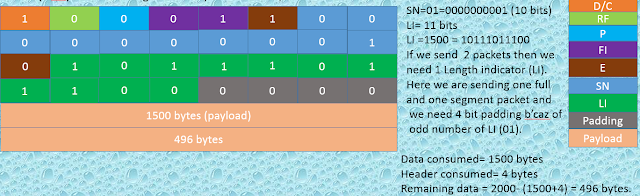
Example- How to make AMD PDU.
PDCP PDUs – 1500, 900,
800,200,300,400,1000,1700,700,100
(Packets/data)
In 1st TTI (1 ms)-
MAC
is asking for 2000 bytes for the 1st
packet.

In 2nd TTI, MAC is asking for 4815 bytes for the 2nd packet.


In 3rd TTI, MAC is asking for 804 bytes for the 3rd packet.

Now this we have transmitted to the other side and we are expecting acknowledgement (status) whether the packets are successfully received or not.
STATUS (Control) PDU -
STATUS PDU consists of a STATUS PDU
payload and a RLC control PDU header.
RLC control PDU header consists of
a D/C and a CPT(Control PDU Type)
field.
The STATUS PDU payload starts from
the first bit following the RLC control PDU header, and it consists of one
ACK_SN and one E1,
zero or more sets of a NACK_SN,
an E1 and an E2, and possibly a set of a SO start and a
SO end for
each NACK_SN. When necessary one to seven padding bits are included in the end
of the STATUS PDU to achieve octet alignment.
When there is control PDU the D/C
field should be ‘1’ and followed by CPT (‘000’ means it is control PDU). When
E1=0 means no negative acknowledgement but When E1=1, meaning is negative
sequence number . So if 6 negative sequence number are received that means
there will be 6 Extension bit (E1). So that other guy will understand that 6 packets are missing. But what is meaning of
E2,SO start and SO end ?.
We
have transmitted a packet ,other guy sends a negative acknowledgement . We
started retransmitting. At the time of retransmitting MAC layer asked that make two piece in two different TTI. If
this two pieces are sending , instead of two pieces again one piece is missing
, then SO start and SO end will explain which part is missing. So, When
E2=0 that means no SO start and SO end but when E2=1 that means there will
be SO start and SO end, means full sequence number is not missing (partially
missing) that is only SO start and SO end is missing.

Case1:
Assume that
above all the three packets are successfully received at other side.
Acknowledgement for all the three
PDUs :

Case2:
Assume that above out of three packets two (1st and 3rd packets) are successfully received and 2nd packets (Full packet) is missing. Then the acknowledgement would be-
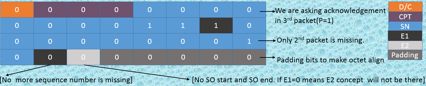 |
When E1 =0 that means no more sequence number is missing. So we have only one sequence number (2nd packet) is missing.
E2 will tell whether the missing
sequence number is completely missing partial missing. Partially missing is not
possible because we have never segmented it. So E2
is set to ‘1’ meaning is followed by any SO start and SO end. When we have
SO start and SO end , we have to use it for partial one is missing. So which
part is missing out of two pieces that will know by E2. But E2=0 means no SO
start and SO end.
Case3:
Assume that above out of three
packets two (1st
and 3rd
packets) are successfully received and 2nd packets is
partially missing. Then
the acknowledgement would be-
Will explain later…………

Previously 2nd packet is missing. So, we need to do retransmission once a again. At the time of retransmission MAC will told to RLC layer what is the PDU size. Assume that it is only asking for 2500 bytes out of 4815 bytes. If we send two piece of information , then sequence number will be same for both the pieces. In this case RF bit should be ‘1’ because segmentation is done.


D/C =0 means it is control PDU and CPT is 000 means it is status PDU and followed by sequence number is 3 only . Because previously we have sent total three(3) packets. Out of 3 packets 2 packet was fully missing. So we have done retransmission 2 pieces for 2nd packet as per MAC required. In that 2nd piece we again asked for acknowledgement. Now we got acknowledgement that again 2nd piece is missing. So full packet is not missing ,only partially missing.
Retransmission :
We successfully acknowledged from
other side that 2nd
packet is completely missing .
If
2nd
packet is missing that means we have to do re-transmission it .

Previously 2nd packet is missing. So, we need to do retransmission once a again. At the time of retransmission MAC will told to RLC layer what is the PDU size. Assume that it is only asking for 2500 bytes out of 4815 bytes. If we send two piece of information , then sequence number will be same for both the pieces. In this case RF bit should be ‘1’ because segmentation is done.
PDCP
PDUs= 1500, 900, 800, 200, 300, 400, 1000, 1700, 100 (
previous example)
Missing
2nd packet(Full) = 4815 bytes
So, now in this TTI MAC is asking 2500 bytes. (Re-transmission for 1st piece.)


When Re-segmentation flag (RF) is
set to be ‘1’, potentially two more field are attached. One is LSF (Last
Segmentation Flag) and second one is segmentation offset (SO).
LSF=0 means is the segmented PDU is
not last byte of AMD PDU and LSF=1 means segmented PDU is the last byte of AMD
PDU.
So, here LSF should be ‘0’ because
first piece. In this case we cutting two piece, for the first piece the LSF
should be ‘0’ and for the second piece the LSF should be ‘1’. But if we cutting
3 piece ,for the first two piece the LSF should be ‘0’ followed by SO and for
the last piece we put LSF=1.
For the first two pieces there may
be potentially to change in the order. So to put them in to order we use
segmentation offset (SO). Here SO=000000000000000 that is 15 bits.
After segmentation offset we need
to have length indicator(LI) and Extension bit (E) based on MAC
instruction.
Now, in the next TTI we are going to send
2nd piece of information.
Now we are going to send second
piece of remaining 1000 bytes + 1700
bytes.
Here, we are asking for
acknowledgement i.e P bit is set to ‘1’. Because we
are retransmitting and tell to other side that we sent two pieces. So tell me
out of two pieces which one is received and which one is not received.
Sequence number will be same as
previous and LSF should be ‘1’ because of last segmented PDU.
In this TTI we are sending 2322
bytes.

Status PDU-
Now we have asked for
acknowledgement in above 2nd
piece. So other side will send the status PDU.
We
retransmitted two pieces for the 2nd
packet. Assume that out of two pieces 2nd piece is again missing.
So what will be the status
PDU-

D/C =0 means it is control PDU and CPT is 000 means it is status PDU and followed by sequence number is 3 only . Because previously we have sent total three(3) packets. Out of 3 packets 2 packet was fully missing. So we have done retransmission 2 pieces for 2nd packet as per MAC required. In that 2nd piece we again asked for acknowledgement. Now we got acknowledgement that again 2nd piece is missing. So full packet is not missing ,only partially missing.
So, E1=0 means no other piece is
missing ,but E2=1 means only partially is missing. That is why followed by SO
start and So end.
SO start is 2488= 100110111000 and
SO end is 111111111111111.
Variables, constants and timers
A)
State variables :
The state
variables used in AM and UM entities in order to specify the RLC protocol.
All
state variables and all counters are non-negative integers.
All
state variables related to AM data transfer can take values from 0 to 1023 for
10 bit SN or from 0 to 65535 for 16 bit SN. AMD
PDUs and UMD PDUs are numbered integer sequence numbers (SN) cycling through
the field: 0 to 1023 for 10 bit SN and 0 to 65535 for 16 bit SN for AMD PDU and
0 to [2[sn-FieldLength] – 1]
for UMD PDU.
The transmitting
side of each AM
RLC entity shall maintain the following state
variables
a) VT(A) – Acknowledgement state
variable
This state
variable holds the value of the SN of the next AMD PDU for which a positive
acknowledgment is to be received in- sequence,
and it serves as the lower edge of the transmitting window. It is initially set
to 0, and is updated whenever the AM RLC entity receives a positive
acknowledgment for an AMD PDU with SN = VT(A).
b) VT(MS) – Maximum send state
variable
This state variable equals VT(A) +
AM_Window_Size, and it serves as the higher edge of the transmitting window.
c) VT(S) – Send state variable
This state variable holds the value
of the SN to be assigned for the next newly generated AMD PDU. It is initially
set to 0, and is updated whenever the AM RLC entity delivers an AMD PDU with SN
= VT(S).
d) POLL_SN – Poll send state variable
The
transmitting side of each AM RLC entity
shall maintain the following counters:
a) PDU_WITHOUT_POLL – Counter
This counter is initially set to 0.
It counts the number of AMD PDUs sent since the most recent poll bit was
transmitted.
b) BYTE_WITHOUT_POLL – Counter
This counter is initially set to 0.
It counts the number of data bytes sent since the most recent poll bit was
transmitted.
c) RETX_COUNT – Counter
This counter counts the number of
retransmissions of an AMD PDU. There
is one RETX_COUNT counter per PDU that needs to be retransmitted.
The
receiving side of each AM RLC entity
shall maintain the following state variables:
a) VR(R) – Receive state variable
This state variable holds the value
of the SN following the last in-sequence completely received AMD PDU, and it
serves as the lower edge of the receiving window. It is initially set to 0, and
is updated whenever the AM RLC entity receives an AMD PDU with SN = VR(R).
b) VR(MR) – Maximum acceptable
receive state variable
This state variable equals VR(R) +
AM_Window_Size, and it holds the value of the SN of the first AMD PDU that is
beyond the receiving window and serves as the higher edge of the receiving
window.
c) VR(X) – t-Reordering
state variable
This state variable holds the value
of the SN following the SN of the RLC data PDU which triggered t-Reordering.
d) VR(MS) – Maximum STATUS transmit
state variable
This state variable holds the
highest possible value of the SN which can be indicated by “ACK_SN” when a
STATUS PDU needs to be constructed. It is initially set to 0.
e) VR(H) – Highest received state
variable
This state variable holds the value
of the SN following the SN of the RLC data PDU with the highest SN among
received RLC data PDUs. It is initially set to 0.
Each
transmitting UM
RLC entity shall maintain the following state
variables:
a) VT(US)
This state variable holds the value
of the SN to be assigned for the next newly generated UMD PDU. It is initially
set to 0, and is updated whenever the UM RLC entity delivers an UMD PDU with SN
= VT(US).
Each receiving UM RLC entity shall
maintain the following state variables:
a) VR(UR) – UM receive state
variable
This state variable holds the value
of the SN of the earliest UMD PDU that is still considered for reordering. It
is initially set to 0. For RLC entity configured for STCH, it is initially set
to the SN of the first received UMD PDU.
b) VR(UX) – UM t-Reordering
state variable
This state variable holds the value
of the SN following the SN of the UMD PDU which triggered t-Reordering.
c) VR(UH) – UM highest received
state variable
This
state variable holds the value of the SN following the SN of the UMD PDU with
the highest SN among received UMD PDUs, and it serves as the higher edge of the
reordering window. It is initially set to 0. For RLC entity configured for
STCH, it is initially set to the SN of the first received UMD PDU.
B)
Constants
a) AM_Window_Size
This constant is used by both the
transmitting side and the receiving side of each AM RLC entity to calculate
VT(MS) from VT(A), and VR(MR) from VR(R). AM_Window_Size = 512 when a 10 bit SN
is used, AM_Window_Size = 32768 when a 16 bit SN is used.
b) UM_Window_Size
This constant is used by the
receiving UM RLC entity to define SNs of those UMD PDUs that can be received
without causing an advancement of the receiving window. UM_Window_Size = 16
when a 5 bit SN is configured, UM_Window_Size = 512 when a 10 bit SN is configured
and UM_Window_Size = 0 when the receiving UM RLC entity is configured for MCCH,
MTCH, SC-MCCH, SC-MTCH or STCH.
C)
Timers
The following timers are configured
by RRC -
a) t-PollRetransmit- (suppose 10 ms)
Assume that we are transmitting 10
RLC PDUs- 1,2,3,4,5,6,7,8,9, 10
(p)
In the 10 packet we are putting the
polling bit (p). Sender sending this packet to the receiver and expecting for
the status that out of 10 packets which are successfully received, which are
not successfully received. But problem is this 10 packet also missing. So
receiver guy won’t send acknowledgement. So, what sender will do?
Sender will wait till the time that
is 20 ms
(t-PollRetransmit).
If this timer expired then sender will retransmit the 10th packet once again.
b)
t-Reordering (suppose
35 ms)
Every X amount of
time (suppose 35 ms),
we will reordering the packets and send to higher layer
c) t-StatusProhibit ( Suppose 960 ms)
Status prohibit is set to be two
things- one is as per time and
other is as per amount of data.
As per time –(t –Status prohibit)
Assume that t-status prohibit is
960 ms.
When this value is set ,the receiver can not send acknowledgement for 960 ms
even other guy actually sending the polling bit again because we are
prohibiting the pool.
d) Data_
Status Prohibit (Suppose 24 kb)
After receiving 24 kb of data, we
can send only one status.
D)
Configurable parameters
The following parameters are
configured by RRC-
a) MaxRetxThreshold
This parameter is used by the
transmitting side of each AM RLC entity to limit the number of retransmissions
of an AMD PDU
Means RLC also can have maximum
retransmission threshold exactly like HARQ retransmission. After trying maximum
number of retransmission, RLC raise hand , he can not do anything.
b) PollPDU
This parameter is used by the
transmitting side of each AM RLC entity to trigger a poll for every pollPDU PDUs.
Means whenever we got the poll bit
, we send the acknowledgement.
c) PollByte
This parameter is used by the
transmitting side of each AM RLC entity to trigger a poll for every pollByte bytes.
Means again it will dependent on
polling bit only. If we received polling bit we send the acknowledgement .
d) SN-FieldLength
This parameter gives the UM SN
field size in bits. For UM mode SN is 5 bit /10 bit,
where as in AM mode SN is 10bit/16bit.
Conclusion:
Both
UM RLC and AM RLC , we are maintaining
sequence number.
Point has to be cleared that for
UM sequence number we are not maintaining the reliability, it only maintained
the packet re-ordering. But in AM sequence number used for two purpose one is
reordering, second one is reliability.
 Reviewed by LTE/IMS reference
on
March 12, 2018
Rating:
Reviewed by LTE/IMS reference
on
March 12, 2018
Rating:

No comments: